
Manual


9651 Instructions 2-11-14.doc Page 1 of 2
9002-9651 Installation Instructions (Slimline 3.5” Auto Dimming
Display Twist Off Mount Mirror with HomeLink)
IMPORTANT: Check kit contents and read instructions before installing. For the latest full color instructions please visit
www.brandmotion.com
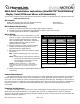
Kit Contents
Slimline Auto Dimming Mirror with 3.5” Display & HomeLink Mirror Harness
Homelink Programming and Information Guide These Instructions
Mirror Removal & Mounting
1. Remove the existing vehicle mirror by twisting it approximately 30 degrees.
2. Carefully twist on the supplied Mirror approximately 30 degrees until it clicks into place.
3. Connect supplied Mirror Harness to supplied Mirror.
Mirror Wiring
1. Use a multimeter to test for vehicle Igniton (+) and
Reverse (+) signals. Typical locations are behind the
driver or passenger side kick panel or under the
dash. Set parking brake, start vehicle, and have an
assistant shift into Reverse while you test for
Ignition and Reverse signals.
2. Plug Mirror Harness into Mirror and route beneath
headliner and down the A-pillar closest to the
Ignition and Reverse signal locations.
3. Splice Mirror Harness wires to the following required
connections:
Red - Ignition controlled power 12v+ when key is
ON
Black - Chassis ground. A ground bolt is commonly
found in the front kick panel area with other
wires attached; in some cases you may
need to supply a new screw.
Green - Connect to Reverse (+) 12V power.
NOTE: While not a required connection, connecting Reverse
disables the vehicle’s auto dim function while vehicle is in
reverse.
4. Connect female RCA plug on supplied Mirror Harness to male
camera RCA.
Camera Requirements
The camera signal must be strong enough for the mirror to detect signal when reverse is engaged. We recommend
that the camera be connected to mirror prior to installation to confirm compatiblity. Best results are on cameras that
have a 0.8- 1.6v DC coming out of video composite lead (commonly a yellow RCA jack). Depending on camera output it
may require reverse to be supplied by a 12v switched ignition rather than reverse feed. To test this use a multimeter set
to DC and connect the (-) lead to the camera RCA shield and the (+) lead to the camera RCA tip with the camera
powered ON.
Powering Up the Camera
The mirror stays ON for over 1 second when reverse is disengaged, and if the camera is connected to the reverse
tail lamp then the screen will flash Blue. If the camera does not power up instantly when the vehicle is shifted into
reverse, the screen will not detect the camera and will not display an image. For these reasons we recommend that the
camera be connected to Ignition (+).
Mirror & Mirror Harness Pinout
PIN
MIRROR
WIRE
COLOR
MIRROR
HARNESS
WIRE COLOR
FUNCTION
1
Purple
White
Video (+)
2
White
Brown
Video (–)
3
N/A
N/A
Not used
4
N/A
N/A
Not used
5
N/A
N/A
Not used
6
Red
Red
Ignition (+)
7
Orange
Green
Reverse (+)
8
Black
Black
Ground
9
N/A
N/A
Not used
10
N/A
N/A
Not used
These instructions only pertain to functions on the supplied
mirror and do not support other vehicle features.