
Installation Guide

Safety+PLUS ADVANTAGE
®
COATED STAINLESS STEEL GAS CONNECTORS
INSTALLATION INSTRUCTIONS
DO NOT INSTALL THIS PRODUCT UNTIL YOU HAVE READ AND UNDERSTAND
ALL INSTRUCTIONS!
The Safety+PLUS ADVANTAGE™ coated stainless steel gas connector combines two
state-of-the-art technologies to deliver a superior gas connector for your home and
family. Safety+PLUS ADVANTAGE gas connectors feature an advanced corrosion
resistant coating called ProCoat®. A proprietary polymer coating, ProCoat is specially
engineered to resist the corrosion from harsh chemicals found in household cleaning,
plumbing repair and masonry products. Approved for indoor and outdoor use, ProCoat
is formulated to resist the harsh effect of UV rays and salt.
Safety+PLUS® excess ow valves (EFV), an automatic safety valve for gas, utilize a
patented magnet-based excess ow technology. In the event of a gas line rupture or
disconnection at the appliance, the Safety+PLUS valve immediately restricts gas ow to
a non-hazardous level (a bypass ow) to avert the potential for a dangerous release of
gas into the home. Only after the gas line has been properly repaired, the bypass ow
automatically resets the valve, allowing gas ow to resume to the appliance.
• Use only on low pressure natural and LP gas piping systems. DO NOT USE on
pipelines or piping systems that transfer or move liquids, including high-pressure
liquid propane.
• Use only with gas line pressures at a minimum of 4” water column (W.C.) and not
greater than 14” W.C. (1/2 psig) at the stub out.
• Use only in connection with residential and commercial gas appliances, where
installation is immediately downstream of the gas supply stub out and manual gas
shut-off valve.
Tools Needed for Installation:
• (2) 10" adjustable wrenches
• Pipe dope or gas pipe thread tape
• Leak detection solution
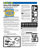
SIZING THE CONNECTOR TO THE APPLIANCE
1. Measure the distance between the gas supply stub out and the appliance.
Add 2 – 3 inches to the measured distance for appropriate connector length for the
installation. (See Fig. A)
2. Identify the maximum (gas) input rating of the
appliance (refered to as “input rating”).
Manufacturer’s label, located near the gas inlet
of the appliance will contain this information.
(See Fig. B) Contact the appliance manufacturer
if you are unsure of the correct rating for the
appliance.
3. Using Chart 1, select the gas connector with the
maximum ow capacity that is HIGHER than the
input rating of the appliance. However, select the
gas connector with the maximum ow capacity
that is CLOSEST TO the input rating of the
appliance. (Figure C)
WARNING: The maximum gas input rating of the
appliance must be within the ow capacity range
of the connector. If the Safety+PLUS gas
connector is not properly sized to the application,
the Safety+PLUS connector may not activate in
the event of a gas line rupture or disconnection.
If the Safety+PLUS gas connector is under sized
for the appliance, may activate prematurely
restricting gas ow during normal operation of
the appliance.
4. Finally, select the connector with the end ttings
that match the outlet of your manual gas shut-off
valve and the gas inlet to the appliance. (Figure D)
NOTE:
All Safety+PLUS valves require minimum inlet pressure of 4” W.C. and are
rated at a maximum inlet pressure of 1/2 psig. (14” W.C.). Flow rates given
are for 0.6 specic gravity natural gas with an average heating value of 1000
BTU per cubic foot; therefore, 1,000 BTU/Hr is equal to 1 SCFH (standard cubic
foot per hour).Chart to be used in accordance with the local plumbing codes and
with reference to IAPMO/ANSI UPC 1-2003; NFPA 54/ANSI Z223.1 - National
Fuel Gas Code.
INSTALLATION INSTRUCTIONS
SAFETY PRECAUTIONS:
1.
Read and follow all installation instructions carefully.
When in doubt, call a licensed plumber or your local
gas company.
2. DO NOT reuse the gas connector or ttings.
The connector, ttings and valve are designed for
use on original installation only. Removal of
connector and additional handling may have
damaged connector making it unsafe for reuse.
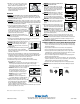
3. DO NOT use this gas connector on appliances
equipped with rollers or casters. (Figure E)
This connector is designed for limited movement
after installation. Repeated bending, exing or
extreme vibration can cause metal fatigue. DO NOT
repeatedly move appliance for cleaning
once installed.
4. AVOID connector contact with foreign objects such as wall studs, electrical wiring,
copper or iron pipe, paneling sheet metal, etc. Gas systems should NOT be used as
electrical grounds. Dissimilar metals should be isolated from each other.
5. Keep cleaning solvents containing ammonia or chlorine away from uncoated gas
connectors. (Figure F) DO NOT store these solutions in closets containing a water
heater or furnace. Chlorine can corrode uncoated stainless steel.
Fig. A
For Residential
and Commercial
Gas Appliances
CONNECTOR
CAPACITY
36”
33,400
63,000
125,000
63,000
GAS APPLIANCE
INPUT RATING
62,500
Fig. B
CONNECTOR
CAPACITY
36”
33,400
63,000
125,000
71,100
GAS APPLIANCE
INPUT RATING
62,500
Fig. C
CONNECTOR
CAPACITY
36”
33,400
63,000
125,000
63,000
GAS APPLIANCE
INPUT RATING
62,500
Fig. D
Gas Connector Maximum Flow Capacity
Part #
EFV Closing
Flow Rate
ID
Color
Code
12” 18” 24” 30” 36” 48” 60” 72”
CSSL 95,000 Btu/Hr 1/4 Purple 48,000 43,800 40,000 36,400 33,400 28,300 24,900 23,100
CSSD 95,000 Btu/Hr 3/8 Green 75,000 70,000 70,000 63,000 65,000 60,500 53,200 49,100
CSSC 195,000 Btu/Hr 1/2 Gold 135,000 130,000 130,000 125,000 125,000 106,000 93,200 86,000
Chart 1
Fig. E
Fig. F