Service Manual for: CJKA-**G CJKA-**G Under-Vehicle Lift® Public Use Wheelchair Lifts Series 01 DOT — Public Use Lift “DOT — Public Use Lift” verifies that this platform lift meets the “public use lift” requirements of FMVSS No. 403. This lift may be installed on all vehicles appropriate for the size and weight of the lift, but must be installed on buses, school buses, and multipurpose passenger vehicles other than motor homes with a gross vehicle weight rating (GVWR) that exceeds 4,536 kg (10,000 lb).
Congratulations We at The Braun Corporation wish to express our fullest appreciation on your new purchase. With you in mind, our skilled craftsmen have designed and assembled the finest lift available. This manual provides service-related material. Refer to the FMVSS No. 403 Quick Reference Installation Sheet for installation instructions, operating instructions and maintenance procedures.
Contents Troubleshooting and Maintenance Lift Terminology ............................................................ 2 Switch and Sensor Locations ..................................... 3 &HUWLÀFDWLRQ &KHFNOLVW 'LDJQRVWLF 3URFHGXUHV ......... 4 Adjustments and Calibration ....................................... 5 7HUPLQDO 6WULS DQG 'RRU 2SHUDWRUV ............................. 6 Floor Level and Inner Roll Stop Adjustments ....... 6-10 /XEULFDWLRQ 'LDJUDP ....................................................
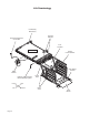
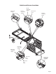
Lift Terminology Lift Mounting Brackets (6) Hydraulic Cylinders Hand-Held Attendant's Control Box Inner Roll Stop Lift Housing Rolling Horizontal Arms STOW DOOR UP DOWN Ca rria WARN ING Push manu T-han and ally dle lock out movein fully to Failurbefore engagplatfo and resulte to drivine rm deplo in lock gplatfo in uninteplatfovehiclrm platfoymen resultrm t. nded rm e. may and/o in deploUninte platfo seriouymennded rm r prope s t may rty bodily dama injury Do ge.
Switch and Sensor Locations Lift Out Limit Switch 73950A Full Out Limit Switch 73950A Lift Out Cam 75776CN Full Out Cam 73775 Pressure Transducer 30426 STOW DOOR UP DOWN WARN ING Push manuaT-hand and lly le lock out movein fully to before Failure engagplatfor and result to driving e platfor m in deployin lock uninteplatfor vehiclm platfor ment. nded m e. result m may Uninte platfor and/orin deploy seriou nded m proper ment s may ty bodily damag injury Do not e.
Certification Checklist Diagnostic Procedures 7KH IROORZLQJ RSHUDWLRQV DQG FRQGLWLRQV PXVW EH IXQFWLRQDOO\ YHULÀHG LQ RUGHU IRU WKH OLIW WR EH )0966 403/404 compliant. If an operation does not function as described or a condition is not met, follow the referenced procedures to correct the problem or contact a Braun Corporation Product Support representative at 7+( /,)7®.
Adjustments and Calibration $GMXVWPHQW 3URFHGXUHV &DOLEUDWLRQ 3URFHGXUHV /LIW 2XW 6ZLWFK The Lift Out Switch stops inward travel of the carriage/platform during Stow function (activated by the housing-mounted Lift Out Cam). Move cam in to increase inward travel. Move cam out to decrease inward travel. LED D25 will be illuminated when the switch is not contacting the cam.
Terminal Strip and Door Operators 3RZHU 'RRU 2SHUDWRUV Install optional power door operators as detailed in the instructions supplied with door operator kit. Route the wires to the pump module and connect to the terminal strip as shown. To Door Openers “Open” Trigger Orange Door Cutout Full Open Black Red Blue 1 2 3 4 5 6 7 8 9 10 1 2 3 4 5 6 7 8 9 10 The pump-mounted terminal strip provides additional inputs and outputs that can be used for optional door operators, beepers, interlocks, etc.
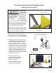
Floor Level and Inner Roll Stop Adjustments Inner Roll Stop Adjustment 'R QRW DGMXVW inner roll stop OLQNDJH URG DW 'R QRW DGMXVW LQQHU WKLV WLPH LinkUROO VWRS OLQNDJH URG age rod adjust/LQNDJH URG DGMXVWment is not ment may result in required unless lift damage. extra usable platform length is needed. If the angle of the inner roll stop (when in the vertical position) restricts the usable platform length for the wheelchair passenger, adjustment of the linkage rod will change the angle.
Floor Level and Inner Roll Stop Adjustments Inner Roll Stop Adjustment 3. Use an Allen wrench to prevent the cam locking screw from turning and loosen the 3/8" serUDWHG ÁDQJH QXW VHFXULQJ WKH lifting arm cam. See Photos D and E. Do not remove the screw or nut. 4. Raise the platform 1" above ÁRRU OHYHO using the manual operation system. 5.
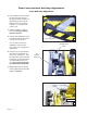
Floor Level and Inner Roll Stop Adjustments Inner Roll Stop Adjustment 'R QRW DGjust the inner roll stop Improper inner roll OLQNDJH URG VWRS OLQNDJH URG unless extra adjustment may usable platresult in lift damage. form length is needed. See Photo G. If the angle of the inner roll stop (when in the vertical position) restricts the usable platform length for the wheelchair passenger, adjustment of the linkage rod will change the angle.
Floor Level and Inner Roll Stop Adjustments Inner Roll Stop Occupied Sensor Adjustment 1. The optimum setting for the inner roll stop occupied sensor adjustment nut is to have just enough pressure to fold and unfold the inner roll stop without triggering the inner roll stop occupied sensor. This provides the most weight sensitive setting while allowing the unoccupied inner roll stop to function correctly. Adjustment Nut 2.
Maintenance and Lubrication Lubrication Diagram Drive Chain and Rollers LO Drive Chain Release Latch SG Hydraulic Cylinder Pivot Points LO Eccentric Shaft Rollers (bearings) LO Hydraulic Cylinder Pivot Points LO STOW UP DOWN Torque Tube Pivot Points LO Lifting Arm Pivot Points Rolling LO Horizontal Carriage Tube Eccentric Slot Area Shaft and DE Carriage Rollers (bearings) LO WARN ING Push manu T-han and ally dle lock out movein fully to Failurbefor engagplatfo and resulte to e drivine rm deplo in
Maintenance and Lubrication Schedule Proper maintenance is necessary to ensure safe, trouble free operation. Inspecting the lift for any wear, damage or other abnormal conditions should be a part of all transit agencies’s daily service program. Simple inspections can detect potential problems. The maintenance and lubrication procedures speciÀHG LQ WKH IROORZLQJ VFKHGXOH must be performed by a Braun authorized service representative at the scheduled intervals according to the number of cycles.
Maintenance and Lubrication Schedule 750 Cycles 1500 Cycles Inspect lift for rattles Correct as needed. Check drive chain tension. Pull out and lock manual release cable. Adjust chain tension as needed. See Drive Chain Adjustment. Inspect inner roll stop and linkage for: • Proper operation. Roll stop should rest solidly on ÁRRU SURYLGLQJ VPRRWK WUDQVLWLRQ • Positive securement • Wear or damage Resecure, replace or correct as needed. See Inner Roll Stop Adjustment Instructions.
Maintenance and Lubrication Schedule 1500 Cycles 4500 Cycles Inspect limit switches for securement and proper adjustment Resecure, replace or adjust as needed. See Switch Adjustment. Inspect carriage, lifting arm and eccentric shaft rollers (bearings) for wear or damage, positive securement and proper operation Correct, replace damaged parts and/or relubricate.
Troubleshooting Diagnosis Chart WARNING Troubleshooting and repair procedures must be performed DV VSHFLÀHG E\ DXthorized service personnel only. Failure to do so may result in serious bodily injury and/or property damage. FUNCTION 1.00 NO OPERATION 2.00 Pump Runs But Will Not Lift Platform 3.00 PUMP DOES NOT RUN WITH MANUAL OVERRIDE OR REMOTE If a problem occurs with your lift, discontinue operation immeGLDWHO\ 'R QRW attempt repairs yourself.
Troubleshooting Diagnosis Chart FUNCTION 4.00 LIFT WILL GO UP WITH OVERRIDE SWITCH BUT NOT WITH REMOTE 5.00 LIFT WILL NOT GO DOWN WITH MANUAL OVERRIDE OR WITH REMOTE OR GOES DOWN SLOWLY OR DRIFTS DOWN BY ITSELF 6.00 LIFT WILL GO DOWN WITH OVERRIDE BUT NOT WITH REMOTE 7.00 LIFT WILL NOT GO OUT WITH OVERRIDE OR REMOTE 8.00 LIFT WILL NOT STOW WITH REMOTE Page 16 POSSIBLE CAUSE REMEDY 4.
Troubleshooting Diagnosis Chart FUNCTION 9.00 BARRIER WILL NOT OPERATE UP OR DOWN WITH REMOTE OR OVERRIDES 10.00 BARRIER OPERATES WITH OVERRIDES BUT WILL NOT GO UP WITH REMOTE 11.00 BARRIER OPERATES WITH OVERRIDES BUT WILL NOT GO DOWN WITH REMOTE 12.00 SWITCHES DO NOT ACTIVATE LED(S) 13.00 DOORS DO NOT OPEN 14.00 DOORS DO NOT CLOSE POSSIBLE CAUSE REMEDY 9.11 Bad circuit breaker Check for proper operation of Below Stow switch. 9.12 Poor plug connections Remove weight from platform.
Troubleshooting Diagnosis Chart CONTACT REMOVAL 1. Remove orange wedge using needle nose pliers or a hook shaped wire to pull wedge straight out. Page 18 2. To remove the contacts, gently pull wire backwards, while at the same time releasing the locking ÀQJHU E\ PRYLQJ LW DZD\ IURP WKH contact with a screwdriver. 3.
Wiring Schematic BAR DN STOW / GND SENS SAFETY INBRD BAR FLOOR LVL A2 POWER PACK / LIFT HOUSING HARNESS #73910A-1600 1 2 3 4 5 6 7 8 1 2 3 4 5 6 7 8 B2 T2 ALARM ALARM IGN PWR SW PWR LIFT OUT FLOOR LVL U1 W BK MAT MAT W #30947A #32426A A B C A B C NOT USED R BK R BK OR BU / GN 1 2 3 4 BAR UP PWR BAR DN PWR BAR DN SW PWR PLATFORM LIGHTS CIRCUIT BREAKER BU OR BU / GN 1 2 J2 R BK 1 2 A B C P2 NO W C R BK 6 5 4 3 2 1 BAR DN MOTOR SOLENOID W W JUNCTION M MOTOR RELAY SOLENOI
U Li nfo Sc ft ld he Wi fo m rin r: at g ic Hydraulic Parts List Item Qty. Description Part No.
Hydraulic Diagram 1 38 39 40 13 11 26 2 18 12 8 35 7 11 Arrow must face pump 9 3 32 10 27 31 28 29 33 30 Fr 6 on tC yli nd er 34 16 4 Arrow must face pump 14 27 25 5 15 28 29 24 37 23 36 Re ar Cy lin de r 34 22 21 17 20 19 Page 21
Pump Module Parts List Item Qty. Description Part # 1 1 Pump Assembly, M259 87060 2 1 Adapter, 1/4” Male NPT x 7/16-20 Male JIC 37° 10130 3 1 Hose Assembly, 1/4”- F. Swivel 7/16-20 JIC 37° 32785A-202 4 1 Fitting, 90° - 7/16-20 Male JIC 37° x 1/4” Male NPT 87569 5 1 Coupling, Hydraulic Quick Connect x 1/4” Female NPT 87614 6 1 Fitting, 3/8” Male NPT x 3/8” Barbed 87618 7 1 Tubing, 3/8” x 5/8”, Tygothane - Clear 82066R012 8 2 Clamp, Hose - 5/8” O.D.
Pump Module Diagram 13 7 28 8 9 OW ST OR DO UP WN DO 12 8 "VALVE T" WIRE ON ELECTRICAL BOARD 14 6 11 TO DOWN VALVE 15 17 1 33 18 47 "PUMP T" WIRE ON ELECTRICAL BOARD 39 19 TO DOWN VALVE 32 16 18 38 10 46 35 "12V" WIRE ON ELECTRICAL BOARD "GROUND" WIRE ON ELECTRICAL BOARD INLINE FUSE HOLDER 37 40 45 34 "12V PWR" WIRE ON ELECTRICAL BOARD 35 36 INLINE FUSE HOLDER 25 43 23 21 22 INLINE FUSE HOLDERS 2 24 5 25 31 44 24 4 32 26 3 24 27 42 24 29 30 20 41 Page 23
Pu Un m fo E x p ld p M fo V lod od r: ie e u w d le Complete Lift Exploded View 60 25 7 25 25 65 25 162 76 88 134 133 142 86 65 156 117 129 162 144 143 162 80 25 142 74 114 135 72 162 131 109 25 142 115 148 53 147 129 138 53 73 68 163 53 53 53 162 62 53 75 53 73 136 53 53 141 56 23 65 146 70 71 162 97 61 162 100 108 43 44 43 101 43 45 85 4 27 14 21 39 33 153 38 50 83 78 10 10 102 155 15 4 2 25 154 152 150 47 47 94 39 93 41 37 38 25 49 41
Repair Parts List Item 1 2 3 4 5 6 7 8 9 10 11 12 13 14 15 16 17 18 19 20 21 22 23 24 25 26 27 28 29 30 31 32 33 34 35 36 37 38 39 40 41 42 43 44 45 46 47 48 49 50 51 52 53 54 55 56 57 58 59 60 61 62 63 64 65 66 67 68 69 70 71 72 73 74 75 76 77 78 79 80 81 82 83 84 85 Qty.
Lift Housing Detail Exploded View 25 7 25 25 25 25 135 25 138 163 162 162 162 162 25 4 11 9 77 67 11 10 18 5 12 17 4 67 1 26 25 83 4 27 13 25 67 153 123 14 22 21 132 67 78 10 8 16 10 102 155 15 4 2 25 154 152 6 6 6 39 3 25 25 24 Page 26 25
Lift Carriage Detail Exploded View 43 44 43 43 45 43 85 83 25 89 137 19 50 48 149 25 17 92 149 84 85 89 137 39 34 38 39 33 33 48 39 57 38 50 83 12 20 39 12 92 34 46 42 81 25 59 34 37 36 35 40 25 150 25 150 47 47 42 81 31 50 48 160 41 37 46 94 39 93 94 40 38 25 49 37 36 41 37 28 30 82 105 87 158 32 159 102 161 104 161 87 29 161 116 38 112 34 104 161 25 95 35 105 25 25 48 50 112 103 32 Page 27
Lift Platform Detail Exploded View 60 162 142 156 117 162 144 143 162 142 162 142 115 148 53 53 53 53 53 53 53 162 62 53 53 141 146 97 61 100 100 108 101 118 110 100 98 37 41 25 107 100 63 66 145 113 37 96 41 64 63 100 113 66 125 89 151 25 90 100 100 10 98 122 129 53 53 53 53 53 53 54 53 139 55 119 120 79 58 157 80 143 74 114 72 58 131 109 147 129 73 68 75 73 136 56 23 65 70 71 Page 28 53 53 53 53 125 113 86 65 128 51 164 100 118 76 88 134 13
"Providing Access to the World" ® Over 300 Braun Dealers Worldwide ® "Providing Access to the World" International Corporate Hdqrs: P.O.
Series 01 Service Manual for: CJKA-**G Under-Vehicle Lift® Public Use Wheelchair Lifts Braun “Worry-Free” Three-Year Limited Warranty The Braun Corporation of Winamac, Indiana, warrants its wheelchair lift against defects in material and workmanship for three years, providing the lift is operated and maintained properly and in conformity with this manual.