Braun UVL® Under Vehicle Wheelchair Lifts L V U Owner's Manual for: UVL ® Series Under Vehicle Wheelchair Lifts Including Models: • UVL603A • UVL603B • UVL603E • UVL604XA • UVL604XB • UVL604XC • UVL604XD • UVL855R • UVL855RH Note to Dealer: Provide this manual to the consumer. See inside cover for warranty/registration information. and Special Order UVL® Series Lift Models WARNING Ow ner 's Ma nu al ® "Providing Access to the World" ® Braun UVL Series International Corporate Hdqrs: P.O.
Congratulations We at The Braun Corporation wish to express our fullest appreciation on your new purchase. With you in mind, our skilled craftsmen have designed and assembled the finest lift available. This manual includes safety precautions, lift operating instructions, manual operating instructions, and instructions for maintenance and lubrication procedures.
Table of Contents Lift Terminology UVL® 600 Series Lift Terminology Illustration ............ 2 Manual Bridge Plate Operating Instructions ......12 Dual Stationary Handrail Instructions .................13 UVL® 600X Series Lift Terminology Illustration .......... 2 UVL® 850 Series Lift Terminology Illustration ............. 3 Dual Manual Fold “P” Handrail Instructions ......13 Lift Terminology Description General ................................................................
Lift Terminology UVL®600 Series Lift Terminology Illustration Inboard Lift Mounting Brackets (4) Chain Drive Motor Hand Pump (inside cover) Right Left Outboard Hydraulic Cylinder Lift Housing Lifting Arms Rolling Horizontal Arms Roll Stop Actuator T LIF UP T N LIF DOW W STO LIFT R DOOSE CLO 81812 WA RN ING Push manu T-han and ally dle lock out movein fully to Failubefor enga platfo and resulre to e drivin ge rm deplot in lock gplatfo in unint platfovehicrm platfoymen resul rm t. ende rm le.
Lift Terminology UVL®850 Series Lift Terminology Illustration Inboard Lift Mounting Brackets (4) Chain Drive Motor Hydraulic Cylinder Lift Housing Left Right Outboard Inboard Roll Stop (Bridge Plate) Hand Pump (inside cover) Manual Fold “U” Handrails with Shields T LIF UP T N LIF DOW W STO LIFT R DOOSE CLO 81812 Roll Stop Actuator WA RNI NG Push manu T-han and ally dle lock out movein fully to Failurbefor engagplatfo and resulte to e drivine rm deplo in lock gplatfo in unint platfovehicrm pl
Lift Terminology Lift Components: Refer to the Lift Terminology Illustrations on pages 2 and 3. Pump Module: The remote mounted pump module consists of the main hydraulic pump, the manual hand pump, the logic control board and other electrical components that power the lift electric/hydraulic systems. Hand-held Switch Control Box: The standard hand-held control switchbox is connected to the pump module. The control box is equipped with four push-button switches, (UP, DOWN, STOW, and DOOR CLOSE).
Lift Operation Safety Safety Symbols SAFETY FIRST! Know That.... All information contained in this manual and supplements (if included), is provided for your safety. Familiarity with proper operation instructions as well as proper installation and maintenance procedures are necessary to ensure safe, troublefree operation. Safety precautions are provided to identify potentially hazardous situations and provide instruction on how to avoid them.
Lift Operation Safety Lift Operation Safety Precautions (continued) WARNING Load and unload clear of vehicular traffic. WARNING Do not overload or abuse. The load rating applies to both the raising and lowering functions - continuous lifting capacity is 750 lbs. WARNING Do not operate or board the lift if you or your lift operator are intoxicated. WARNING Do not raise front wheelchair wheels (pull wheelie) when loading (boarding) the platform.
Lift Operation Safety Lift Operation Safety Precautions (continued) WARNING Keep clear of any hydraulic leak. WARNING Failure to follow these safety precautions may result in serious bodily injury and/or property damage. Pre-Lift Operation Notes WARNING Read and become familiar with all lift operation safety precautions, pre-lift operation notes, operating instructions and manual operating instructions prior to operating the lift.
Pre-Lift Operation Notes platform raises. Note: The lift platform will not raise if the roll stop is not in the UP position. This is a built-in safety feature. fully unfolded before the front and rear wheelchair wheels (or standee) have crossed the roll stop. The LIFT DOWN function lowers the platform to ground level. The outboard roll stop automatically unfolds to ramp (horizontal) position when the platform contacts the ground to allow the wheelchair passenger on or off of the lift.
Pre-Lift Operation Notes Further details and instructions for operation of manual bridge plates are provided in the Manual Bridge Plate Operating Instructions (see page 12). Handrails: UVL lift models may be equipped with one of three types of handrails - Stationary Handrails, Manual Fold “P” Handrails or Manual Fold “U” Handrails with Safety Side Shields. Handrails are standard equipment on most lift models and optional equipment on others.
Pre-Lift Operation Notes Operation Procedure Review: The wheelchair lift user and/or attendant should review the safety precautions and operation procedures appearing in this manual with your wheelchair lift sales representative (dealer), before attempting lift operation. Become familiar with the proper operation of your lift before operating the lift by yourself. sales representative should also instruct and demonstrate manual operation procedures.
Lift Operating Instructions Lift Control Switches: The UVL® logic control system provides fully automatic operation of all lift functions as well as optional automatic door operators (if so equipped). Lift functions can be performed from any position the platform happens to be in at the time the switch button is pushed. There are two types of hand controls available for the UVL - the standard hand-held control switchbox, or the optional remote control.
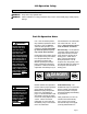
Manual Bridge Plate Operating Instructions A Vertical Bridge Plate Engagement Engagement Notch B Floor Level Bridge Plate Manual Bridge Plate Platform at Stow Level The bridge plate bridges the gap between the lift platform and the vehicle floor when the lift platform is raised fully (positioned at floor level), as well as serving as an inboard roll stop. Manual bridge plates are attendant operated. The bridge plate rests on the platform surface when the lift is in the stowed position (see Photo A).
Dual Stationary Handrail Instructions Stationary handrails remain in the upright (vertical position) at all times. Handrail access slots are provided in the lift housing cover. Access slots are incorporated in the vehicle floor or stairwell during lift installation procedures. The handrails travel in and out of the access slots as the platform carriage assembly retracts and extends. Keep clear of the handrail access slots during lift operation.
Dual Manual Fold “U” Handrail (with Shield) Instructions Folding “U” handrails (with safety shield) are manually operated. The handrails rest on the platform when the lift is not in use. The handrails must be folded down to the platform (horizontal position) before stowing the lift. Note: The bridge plate (inboard roll stop) must be folded down to the platform (horizontal position) before the handrails are folded down.
Manual Operating Instructions The UVL has the capability of being manually operated. If you experience power or equipment failure, refer to the Manual Operating Instructions to manually operate the lift. Refer to the Lift Operating Instructions for all normal lift operation procedures (such as loading and unloading passengers).
Manual Operating Instructions WARNING Push T-handle in fully and manually move platform in and out to engage platform lock before driving vehicle. Failure to lock platform may result in unintended platform deployment. Unintended platform deployment may result in serious bodily injury and/or property damage. Note: The lift platform must be pushed back into its carriage compartment at least half-way before reverting back to normal (powered) operation.
Manual Operating Instructions Hand Pump Handle To Manually Raise Platform To Floor Level: A B Note: Disregard procedures for manually moving the platform in or out if not applicable. Hand Pump 1. Remove pump handle from clips on side of power pack (or other storage location). Open Close (Down) (Up/Stop) 2. Place handle through pump cover access slot and into hand pump. Stroke hand pump until platform reaches floor height (see Photo C).
Manual Operating Instructions Hand Pump Handle To Manually Lower Platform To Ground Level: A B Note: Disregard procedures for manually moving the platform in or out if not applicable. Hand Pump When lowering platform from floor level: Open Close (Down) (Up/Stop) 1. a. Pull “T” handle release cable outward and b. turn “T” handle to lock platform into the released position (see Figure 1). 2. Pull platform out fully (until it stops), if applicable.
Manual Operating Instructions To Manually Move Platform Inward (Retract) To Stow Position: 3 Read Platform Carriage Assembly Drive Chain Reengagement Procedure section on page 16! WARNING 2 1. Position (raise or lower) platform to stow level (height) using procedures outlined on pages 17 and 18. TO LO CK WA RN ING 2. Pull “T” handle release cable. See Figure 1. 3. Turn “T” handle to lock platform in the released position. See Figure 1.
Manual Operating Instructions To Manually Lower Outboard Roll Stop: Note: Actuator shown exploded from lift for clarity. 1. Remove hairpin cotter from detent pin. Roll Stop Actuator Hairpin Cotter 1 Detent Pin 2 2. Remove detent pin to detach roll stop actuator from roll stop. 3. Push roll stop to the down (ramp - horizontal) position.
Maintenance and Lubrication Maintenance is necessary to ensure safe and trouble-free lift operation. General preventive maintenance consisting of inspections of your lift system and cleaning the lift should be a part of your routine. When cleaning the lift, pay special attention to the roll stop opening, platform surface and bottom of platform. If mud, ice and/or snow build-up is apparent on platform surface, clean the area prior to use. Do not spray water inside of lift housing.
Decals Remember — the lift is only as safe as the operator! WARNING Replace missing, worn or illegible decals. Failure to do so may result in serious bodily injury and/or property damage. Lift-posted decals are shown at right. Part numbers are provided for all decals. Inspect your lift for any missing, worn or illegible decals. Call 1-800THE LIFT for replacements. WARNING #81813 Keep clear of stepwell when operating lift.
Warranty/Registration Instructions Immediately upon receiving your lift, examine the unit for any damage. Notify the carrier at once with any claims. cover of this manual. The Braun Serial No./Series No. identification tag (shown below) is located on the left platform side plate (outboard end). This I.D. tag contains the product identification information provided on the Warranty/Registration card. Record the information in the space provided below.
"Providing Access to the World" ® Over 300 Braun Dealers and Distributors Worldwide ® "Providing Access to the World" International Corporate Hdqrs: P.O.
Braun UVL® Under Vehicle Wheelchair Lifts L V U Braun “Worry-Free” Three-Year Limited Warranty The Braun Corporation of Winamac, Indiana, warrants its wheelchair lift against defects in material and workmanship for three years, providing the lift is operated and maintained properly and in conformity with this manual.