Service Manual for: C8A Century HZg^Zh Public Use Wheelchair Lifts Series 03 DOT — Public Use Lift “DOT — Public Use Lift” verifies that this platform lift meets the “public use lift” requirements of FMVSS No. 403. This lift may be installed on all vehicles appropriate for the size and weight of the lift, but must be installed on buses, school buses, and multipurpose passenger vehicles other than motor homes with a gross vehicle weight rating (GVWR) that exceeds 4,536 kg (10,000 lb).
Congratulations We at The Braun Corporation wish to express our fullest appreciation on your new purchase. With you in mind, our skilled craftsmen have designed and assembled the finest lift available. This manual provides service-related material. Refer to the FMVSS No. 403 Quick Reference Installation Sheet for installation instructions, operating instructions and maintenance procedures.
Contents Troubleshooting &HUWLÀFDWLRQ &KHFNOLVW 'LDJQRVWLF 3URFHGXUHV ....... 2-3 /LIW (OHFWULFDO 6FKHPDWLF .............................................. 4 /LIW :LULQJ 'LDJUDP ...................................................... 5 6ZLWFK DQG 6HQVRU /RFDWLRQV ..................................... 6 /&' (UURU &RGHV .......................................................... 7 +\GUDXOLFV +\GUDXOLF 6FKHPDWLF .................................................... 8 +\GUDXOLFV 3DUWV /LVW .......................
Certification Checklist Diagnostic Procedures 8VH WKH IROORZLQJ DGMXVWPHQW SURFHGXUHV VKRXOG WKH OLIW QRW IXQFWLRQ DV GHVFULEHG LQ WKH FHUWLÀFDWLRQ FKHFNOLVW 7KHVH SURFHGXUHV PXVW EH IROORZHG LQ RUGHU IRU WKH OLIW WR EH )0966 FRPSOLDQW 9HKLFOH PRYHPHQW LV SUHYHQWHG XQOHVV WKH SODWIRUP LV IXOO\ VWRZHG 9HULI\ OLIW VWRZHG VLJQDO SLQ RQ WKH SXPS PRGXOH KDV D YROW RXWSXW VLJQDO IURP OLIW 25 SLQ KDV D JURXQG VLJQDO IURP OLIW GHSHQGV RQ LQWHUORFN XVHG 5HIHU WR WKH LQWHUORFN L
Certification Checklist Diagnostic Procedures 7KH LQQHU UROOVWRS ZLOO QRW UDLVH LI RFFXSLHG &DOO 3URGXFW 6XSSRUW 7KH RXWHU EDUULHU ZLOO QRW UDLVH LI RFFXSLHG &DOO 3URGXFW 6XSSRUW 9HULI\ SODWIRUP OLJKWLQJ ZKHQ OLIW LV GHSOR\HG 5HSODFH EXOE V LQ WKH OLJKW KRXVLQJ &KHFN IXVH DPS IXVH RQ FLUFXLW ERDUG ) $Q DXGLR ZDUQLQJ DQG YLVXDO ZDUQLQJ IRU SXEOLF OLIWV ZLOO DFWLYDWH LI WKH WKUHVKROG DUHD LV RFFXSLHG ZKHQ WKH SODW IRUP LV DW OHDVW EHORZ ÁRRU OHYHO
Lift Electrical Schematic LIFT SWITCH BOX NOTE: ALL WIRES ARE 22 GA. UNLESS OTHERWISE NOTED.
Lift Wiring Diagram BK(18) 5 4 3 2 1 6-COND WIRE CODE NO. P20 COLOR RED 1 2 BLACK 4 GREEN 3 J20 RD(20) 1 2 RD(20) GN(20) RL5 BK(20) J21 RD(20) 915-A2539NA COM. N.O. NO COM NC N.C. C-H C5 J31 P31 GN(20) WH(20) 4 4 3 1 2 2 1 4-COND WIRE CODE NO. RED(20) 2 BLACK(20) 3 GREEN(20) COM. N.O.
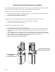
Switch and Sensor Locations Threshold Strip Switch 31221A (Qty. 2) *Stow Microswitch 23184 (Qty. 2) UP FOLD UNFOLD N DOW Inboard Left Right Outboard *Rotary Position Sensor 31194A *IB Occupancy Microswitch Assy. 31643A *IB Raised Magnetic Sensor 31030A45 *IB Raised Magnet 30662 *Outboard Barrier Link / Slide Magnet Assy.
LCD Lift Codes Listed below are codes that the lift controller outputs during lift operation. The codes will be displayed on an LCD screen located on the lift control board inside the pump module. See the Manual Operating Instructions in the operator's manual for pump cover removal instructions.
Hydraulic Schematic Orifice Orifice Down Valve Lifting Relief Valve 2500 PSI Secondary Valve M Folding Relief Valve 1900 PSI 800 PSI Opposite Pump Cylinder Pump Side Cylinder BACKUP PUMP Description PUMP Symbol Fixed Displacement Pump Pump Motor Hydraulic Port M 2 Way 2 Position Solenoid Valve Backup Pump Pressure Compensated Flow Control Single Acting Cylinder Relief Valve Check Valve Filter Screen Unfold Orifice Vented Reservoir Manual Shutoff Valve Page 8 Description Symbol
Hydraulics Parts List Item Qty.
Hydraulics Diagram 1 2 4 3 27 27 6 5 Hydraulic Pump Motor 21 10 26 26 7 17 14 22 23 15 Backup Pump 18 Pump Side Cylinder Opposite Pump Cylinder 13 12 Manual 16 20 19 24 25 28 28 29 Page 10 30
Pump Module Parts List Item Qty. Description 1 Pump Module (complete), 12 Volt, Rear 1 1 Pump Assembly (M268-0112) 12V-120G - Dual Relief (Includes Items 2 & 3) 2 1 Power Cable, Up Solenoid to Motor 3 1 Solenoid, Up - 4-Post - Prestolite 4 1 Diode Assembly, Up Solenoid Part No. 985-A2516RNA 30915-12V 29049 28308 73906A 5 3 Rivet, Pop, SD43BS - 1/8” - .13”/.
Pump Module Diagram 44 Pump Mounting Bolts Apply red #271 Thread Locker Locktite® to the three pump mounting bolts (items 37 and 38) if a blue nylon patch is not SUHVHQW RQ WKH EROWV ZKHQ UHWURÀWWLQJ DQ M268 pump assembly. Loctite® is available from The Braun Corporation under part number 11522-1.
Repair Parts Part Numbers of Items Dedicated per Lift Model Item Qty. 1 2 3 4 5 6 7 8 9 10 11 12 13 14 15 16 1 1 1 1 1 1 1 1 1 1 1 1 2 1 1 1 Item Qty.
Exploded View 31 52 179 52 98 74 179 62 106 148 21 98 12 34 64 27 33 10 112 58 26 23 28 52 106 74 42 118 180 1 180 140 18 43 180 27 28 114 106 74 113 134 50 180 38 111 104 52 53 53 118 29 113 79 98 112 109 40 140 18 17 100 17 17 100 28 27 17 28 27 134 21 78 53 52 55 53 52 106 74 78 24 2 33 31 35 134 112 109 22 3 52 176 104 134 52 106 74 147 94 89 78 78 94 21 53 91 39 32 37 58 113 115 79 52 154 53 27 108 106 51 57
"Providing Access to the World" ® Over 300 Braun Dealers Worldwide ® "Providing Access to the World" International Corporate Hdqrs: P.O.
Service Manual for: C8A Century HZg^Zh Series 03 Public Use Wheelchair Lifts Century Series Lift Braun “Worry-Free” Five-Year Limited Warranty The Braun Corporation of Winamac, Indiana, warrants its wheelchair lift against defects in material and workmanship for up to five years*, providing the lift is installed, operated and maintained properly and in conformity with this manual.