
Unit installation

14-5
RLC-3 V1.80 Copyright © 1998 Link Communications Inc. 9/17/98
Installation
Place or mount the RBI-1 in close proximity to the Kenwood mobile radio to be used. Connect the
RBI-1 with the provided PG-4H Cable from the 8 pin modular jack marked "RADIO" to the
Kenwood Microphone jack. Only Port 1 (140/DUAL) will support a Dual Band radio. Port 1 is the
only Port the 140 Mhz radio can be connected to.
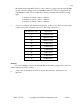
The RBI will support all 4 bands (140/220/440/1200) as follows:
If Port one is filled, Port 2 is for 220 only, Port 3 is for 440 only, Port 4 is for 1200 only. Basically,
if the selected band is unavailable on Port 1 it will go to the port assigned to that band.
Installation instructions are included with the RLC-ICM for connecting it to the IC-900/901
modules.
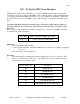
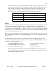
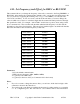
Building the RBI-1/RLC-ICM Cable
It is important to keep your interface cable as short as possible. The cable should never be more
than 6 feet in length; shorter is better.
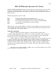
RBI-1 Connector J2 RLC-3 Connections
Pin# - Line Name Pin# - Line Name
___________________________________________________________________________________________________________________________
Connections to serial port on the radio card (top DB-9)
3 - Data ..................... 2 - RLC-3 SPI data output
4 - Clock/Strobe ............... 3 - RLC-3 SPI clock output
9 - Ground ................... 5 - Ground - Required for noise suppression
Connections to the radio port (bottom DB-9)
5 - TX Audio (T Pot) ........... 4 - RLC-3 audio out
6 - RX Audio (R Pot) ........... 5 - RLC-3 audio in
7 - COS from RX ............. 7 - RLC-3 COR input (RBI-1 is active high, RLC-ICM is
low)
8 - PTT to TX ................ 3 - RLC-3 PTT output
9 - Ground ................... 1 - RLC-3 ground connection
2 - RLC-ICM (not RBI-1) PL
Detect Out ............... 2 - RLC-3 PL detect input (optional)
Connections to I/O Board (DB-25)
1 - RBI-1 (not RLC-ICM) Reset .. Open collector output on I/O board (optional)
2 - RBI-1 (not RLC-ICM)
"S" Meter output ........... Analog input on I/O board (optional)
In case it wasn't clear, there is only one connector on the RBI-1 or RLC-ICM that goes to the
RLC-3. It is connected to two different DB-9's on the RLC-3, both of which are on the same radio
port card. The bottom connector provides the audio, COR, PTT and (on the RLC-ICM the PL)