
Unit installation

14-6
RLC-3 V1.80 Copyright © 1998 Link Communications Inc. 9/17/98
connections. The top (serial port) connector provides the control signals. This is not the main
serial port the the RLC-3 motherboard. If you are using the RBI-1, there may also be some
connections to one of the I/O boards.
Setup and Adjustment
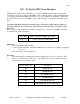
You must install two jumper blocks on header J5 on the radio card that the interface cable is
plugged into or you will not be able to control the RBI-1 or RLC-ICM. Pins 1 and 2 should be
shorted together and pins 3 and 4 should be shorted together. These jumper blocks can be obtained
at most electronics supply stores.
The RBI-1 COR signal is active high. The RLC-ICM COR signal is active low. Set the COR
polarity switch on the radio card accordingly.
Audio receive level from the Kenwood to the Controller is controlled by VR2 (R). The audio level
from the Controller to the Kenwood is adjusted by VR1 (T). Refer to your manuals for additional
adjustments in your controller.
Capacitor C5 (10uF) Inside the RBI-1 Interface must be removed and replaced with a 1uF/25V
Tantalum Capacitor for the Audio to sound correct. Remove capacitors C16 and C17 to keep the
audio from sounding too 'Bassy'.