
Unit installation
15-1
RLC-3 V1.80 Copyright © 1998 Link Communications Inc. 9/17/98
Chapter 15: Serial Controlled (HF) Radio Support
This section describes the controller's interface for serial controlled radios. Most such radios are
for the HF bands, but some such as the FT-736 handle the VHF and UHF bands. The controller's
software will handle frequencies through the 1.2GHz band for radios that support them. When "HF
radios" are referred to in this chapter, other serial controlled radios are also included.
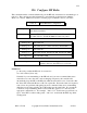
HF Radio Interfacing
The audio in, audio out and PTT connections to the serial controlled radio should be made just like
for a repeater or any other radio, as described in Chapter 1 (they go to the bottom DB-9 connector
on a radio card). If the serial controlled radio has a COR output (from an all-mode squelch), it can
be connected normally as well. If the radio does not have a COR output, set the COR polarity for
that radio port to active high, so the internal pullup will make it always active (or leave it active low
and tie the COR input to ground). This is necessary because the controller normally mutes
incoming audio unless the COR line is active (see command 005 for more information). Note that
having the COR line always active will make the HF receiver timer out, so you might want to
disable the time out timer for that radio port by setting it to zero (with command 020). If it does
time out, you can reset the time out timer by resetting the controller with command 035 (you will
have to exit HF mode to do that).
In addition to the audio in, audio out, COR and PTT signals, you will need to connect the
controller to the radio's serial port, so you can control the frequency and other settings. Before
doing this, execute command 195 so the controller will know not to echo serial characters to the
radio (which can cause then to get into an endless loop). Most serial controlled radios use TTL
level signals, rather than the RS-232 signals that computers, mice, modems, and the controller's
main serial port all use. RS-232 signals switch between +12 and -12 volts, while TTL signals
change from 0 to 5 volts. A few radios use RS-232 level signals. Do not connect an RS-232
serial port to a TTL serial port without an adapter! Adapters to convert TTL signals to RS-
232 signals can be purchased from the radio manufacturers or built from scratch (for less than $10).
Some of these adapters may invert the data (the Kenwood TS-870 for example), just to make it
more confusing. We have schematics for the level converters for some radios; check our web page
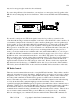
or call us for more information. Once you have connected an adapter to the radio, you can simply
connect the RS-232 serial port on the adapter to the top DB-9 connector on the same radio card
that you have the audio connections to. You must then install a Dallas DS1275 IC into the
socket labeled U8 and make sure that there are no jumper blocks on header J5 on that radio
card (both are underneath the level adjustment pots). The Dallas DS1275 does not come
standard with the RLC-3, but it is available from Link Communications and electronics supply
sources. When using the DS1275, you must connect both the send a receive data lines. The
DS1275 uses the -12V from the data line that goes into the controller to generate the -12V signal it
sends back out. Without that connection, it will send the +12V signals, but not the -12V signals. If
you are using TTL signals, only the data line going out from the controller (and ground) need to be
connected. If the DS1275 works inconsistently or not at all and the pulses at pin 3 of the DS1275
do not look nice and square, try installing a 10K pullup resistor from pin 3 of the DS1275 (or pin 2,
the second from the bottom, of the 4 pin header) to pin 8 of the adjacent op-amp (U3, or any other
5v supply point). The processor is using an open collector output and the pullup inside the DS1275