R SERIES 70 SERVO PRO Version 3.
BRAY Series 70 Servo Pro Operation and Maintenance Manual Table of Contents Bray Series 70 Servo Pro Operation and Maintenance Manual 1.0 1.1 1.2 1.3 1.4 2.0 2.1 2.2 2.3 2.4 2.5 3.0 3.1 4.0 4.1 4.2 4.3 4.4 5.0 5.1 5.1.1 5.1.2 5.1.3 5.1.4 5.1.5 5.1.6 5.1.7 5.1.7.1 5.1.8 5.1.8.1 6.0 6.1 6.2 Safety Information – Definition of Terms..........................................................................2 Hazard-free use.......................................................................................
BRAY Series 70 Servo Pro Operation and Maintenance Manual Safety Instructions - Definition of Terms READ AND FOLLOW THESE INSTRUCTIONS SAVE THESE INSTRUCTIONS ! WARNING indicates a potentially hazardous situation which, if not avoided, could result in death or serious injury. ! CAUTION indicates a potentially hazardous situation which, if not avoided, may result in minor or moderate injury.
BRAY Series 70 Servo Pro Operation and Maintenance Manual ! 1.3 Intended Use WARNING The actuator must only be installed, commissioned, operated and repaired by qualified personnel. The actuator is designed for installation inside the Bray S70 Electric Actuator, and to position an industrial quarter-turn valve. It must be installed according to its intended purpose. The Servo Pro controls the movement of an electric actuator that generates large mechanical forces.
BRAY Series 70 Servo Pro Operation and Maintenance Manual the actuator to change position, which will move the associated control valve to modify the process variable. The process controller continually calculates and transmits the appropriate command signal to the Servo Pro to maintain the process at the desired set point. The Servo Pro simultaneously provides a feedback output signal representing the current actuator position.
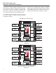
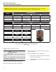
BRAY Series 70 Servo Pro Operation and Maintenance Manual 2.2 Configuration Switches NOTICE Disconnect all electric power to the Servo Pro prior to adjusting configuration switches. Reconnect electric power only after all the configuration switches are in the proper position. The configuration switches are located on the top edge of the Servo Pro Revision F, between the Calibration button and the Status LED.
BRAY Series 70 Servo Pro Operation and Maintenance Manual 2.3 C onfiguration S witch F unction Description Command Signal Input – the signal from the process controller that represents the desired actuator position. Feedback Output Signal – the signal from the Servo Pro that represents the current actuator position. Forward Acting – the actuator will move toward the open direction with an increase in command signal.
BRAY Series 70 Servo Pro Operation and Maintenance Manual 2.5 Previous Revisions of Servo Pro The previous version of Servo Pro (Revision D) has a different physical layout and configuration switch arrangement than Revision F. Revision D does not include terminals for wiring the Local Control Box, or for Torque Switches, or for wiring the Anti-Condensation Heater.
BRAY Series 70 Servo Pro Operation and Maintenance Manual NOTE: The following chart is for configuration of an older model Servo Pro (Rev. D). Please verify that the model you are using is the same model before consulting this chart.
BRAY Series 70 Servo Pro Operation and Maintenance Manual E. Verify (or adjust) the travel stop limits in the actuator a. Bray actuators are shipped with the travel switches in the factory default position - close travel limit set at 0 degrees and the open travel limit set at 90 degrees b. Bray actuators equipped with Servo Pro have the internal feedback potentiometer set in the proper position to match the travel switch factory default (fully close at 0 degrees and fully open at 90 degrees) c.
BRAY Series 70 Servo Pro Operation and Maintenance Manual Transient Suppression c. Electromagnetic Interference (EMI) can result from inductive loads, which can adversely affect electronic circuits. d. Reducing the opening speed of the actuator can allow more precise positioning of the actuator. Appropriately sized surge suppressors should be installed whenever inductive loads such as transformers, relays, solenoids, motors, etc. are operated.
BRAY Series 70 Servo Pro Operation and Maintenance Manual 3.1 Calibration Procedure 4.2 Motor Power LEDs The calibration procedure should be run when the Servo Pro is first commissioned, and anytime that a subsequent change is made to either the Servo Pro Configuration or the actuator in which the Servo Pro is installed. There are two Motor Power LEDs. 1. Engage the actuator handwheel by pulling it outward, and manually move the actuator to the mid-travel position. 2.
BRAY Series 70 Servo Pro Operation and Maintenance Manual 4.4 Status LED Flash Codes Table 3 shows various diagnostic Flash Codes and their descriptions. If more than one advisory condition or error condition exists, only one Flash Code will appear at a time. The first condition must be corrected before the second (or subsequent) Flash Code will appear. Table 3: Status LED flash codes No.
BRAY Series 70 Servo Pro Operation and Maintenance Manual 5.0 Hardware Description The microprocessor-controlled Servo Pro enhances the operation of the S70 actuator by providing full positioning control, supplying an actuator position feedback signal, responding to various switch input conditions, performing self-diagnostics and indicating operational status. The Servo Pro microprocessor eliminates the need to adjust potentiometers during calibration. Calibration is performed by simply pressing a button.
BRAY Series 70 Servo Pro Operation and Maintenance Manual switches 1, 2 and 3. Refer to the configuration Switch Chart in Section 2.2. The potentiometer command signal option is useful to demonstrate an actuator equipped with a Servo Pro when a 4-20 mA DC calibration device is unavailable. ! CAUTION Do not connect any high voltage power to the output signal terminals as damage could result. CAUTION The Servo Pro provides an active (powered) output signal.
BRAY Series 70 Servo Pro Operation and Maintenance Manual ! CAUTION Do not connect any high voltage power to the handwheel switch terminals as damage could result. Engaging the handwheel prevents the actuator motor from becoming energized, but it does not remove electric power from the Servo Pro. Exercise caution to avoid personnel injury or damage to property. 5.1.
BRAY Series 70 Servo Pro Operation and Maintenance Manual NOTICE A torque switch that is broken, improperly wired, or missing from the actuator can result in an open contact which will be interpreted by the Servo Pro as the actuator being at its max torque limit. If the optional torque switches are not installed, select Torque Switch Disable by setting Configuration switch 10 to ON. ! CAUTION Do not connect any high voltage power to the torque limit switch terminals as damage could result. 5.1.
BRAY Series 70 Servo Pro Operation and Maintenance Manual 5.1.8 Control Box Terminal Open / Stop / Close Switch The Servo Pro accepts signals from the optional Local Control Box which may be mounted integrally or remotely. Open – the Servo Pro powers the actuator motor in the open direction The wiring to the local Control Box is connected at the factory and should not require any adjustment by the customer. If a field repair is required, follow the wiring instructions in Section 5.1.8.1.
BRAY Series 70 Servo Pro Operation and Maintenance Manual 6.0 Troubleshooting Guide The Servo Pro is easy to configure and operate, but if problems do occur, the following guide can assist troubleshooting. The first step is to observe the Power LED to verify that the proper electrical power has been connected. Then observe the Status LED and note the Flash Code. If it is not the normal green heartbeat indication, refer to the Status LED Flash Code chart in Section 4.4. 6.
BRAY Series 70 Servo Pro Operation and Maintenance Manual 6.
CONTROLS R A Division of BRAY INTERNATIONAL, Inc. 13333 Westland East Blvd. Houston, Texas 77041 281/894-5454 FAX 281/894-9499 www.bray.com Bray® is a registered trademark of Bray International, Inc. © 2012 Bray International. All rights reserved.