
Manual

Installation and Maintenance Manual
F15/F30 Ball Valves
Date: August 2011 / Page 3 of 5
®
A Subsidiary of BRAY INTERNATIONAL, Inc.
FLOW-TEK, Inc. Tel: 832.912.2300
© 2011 Flow-Tek, Inc.
8323 N. Eldridge Pkwy #100 Fax: 832.912.2301
Houston, Texas 77041 www.flow-tek.com
10. Cycle the valve slowly, with a gentle back and forth
motion, to build gradually to the full quarter turn. By
cycling slowly, the seat lips will assume a permanent
seal shape against the ball. A fast turning motion,
at this point, may cut the seats before they have a
chance to form the proper seal.
11. Test valve, if possible, prior to placing valve hack into
line position. WARNING: If not properly secured,
the valve can separate from the pressure source,
resulting in possible injury. Always join the valve
to companion.
12. flanges of same pressure rating as valve and secure
with a full set of flange bolts.
Table 1
BODY BOLT TORQUE
VALVE SIZE F15 (lb.in.) F30 (lb.in.)
1/2” 140 140
3/4” 140 140
1” 210 210
11/4” 210 210
1-1/2” 550 550
2 550 550
2-1/2” 550 550
3” 550 1000
4” 550 1000
6” 1000 1000
8” 1000 1450
10” 1450 2400
12” 1450 3600
TEST AS FOLLOWS
1. Secure valve to a test future by means of a mating
flange with full bolting and a suitable gasket. Orient
valve so seat to he tested is facing up.
2. Introduce 50 to 100 psig air. Partially cycle the valve,
under pressure, and then slowly close to make sure
the cavity is pressurized (use hearing protection).
Pour water into the upper port to cover the ball
and visually check for bubbles. If bubbles appear,
pour the water out, cycle the valve several times
and recheck. To check for leakage in the other port,
reverse the valve and introduce air pressure to the
port just checked.
3. Check stem seal at this time by coating the gland
area with a soapy water solution. If leakage occurs,
tighten stem seal just until leakage stops.
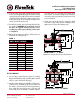
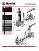
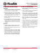
SECTION VIEW ½” - 2” VALVES
Dimensions may be found in product literature
SECTION VIEW 2-1/2” - 12” VALVES
A
D
N-øT
øB
øF
øS
C1
C
E
A
E
D
4-øT
C
øF
C1
øS
øB