
Instruction Manual

Installation and Maintenance Manual
Multiport Threaded and Weld End Ball Valves
Date: May 2011 / Page 1 of 3
®
A Subsidiary of BRAY INTERNATIONAL, Inc.
FLOW-TEK, Inc. Tel: 832.912.2300
© 2011 Flow-Tek, Inc.
8323 N. Eldridge Pkwy #100 Fax: 832.912.2301
Houston, Texas 77041 www.flow-tek.com
INSTALLATION – MAINTENANCE MANUAL
MULTIPORT THREADED AND WELD END BALL VALVES
MPC, MPT, MPS, MPB 130/230/240
USE:
Life of valves can be extended when it is maintained
under normal working conditions and in accordance
with pressure/temperature and corrosion data chart.
VALVE OPERATIONS:
The three way ball valve can be configured into several
options. Generally, flow pattern can be set with a quarter
(90 degree) turn or half (180 degree) turn. Please consult
our flow pattern chart for more information.
A. MANUAL OPERATION
Flow indicator shows the actual valve flow path. Il-
lustration below shows the location of the flow indicator
on the valve stem. Turn the handle 90 degrees or 180
degrees in accordance to your set flow pattern.
B. ACUTATOR OPERATION
Prior to actuator installation, please check the flow path
of the valve by observing the port openings. Mark this
opening on the ball valve prior to actuator installation
in order to get the correct flow orientation. After actua-
tor installation, valve should be checked for valve stem
alignment. Angular or linear misalignment will result in
high operational torque and unnecessary wear on the
stem seal.
GENERAL INFORMATION FOR ON-SITE
INSTALLATION:
• The valve may be fitted in any position on the
pipeline.
• Before installing the valves, the pipes must be
flushed clean of dirt, burrs and welding residues
to prevent damage to the seats and ball surface.
• The pipeline must be free of tension.
INSTALLATION OF THREADED VALVES:
• Use conventional sealant, such as hemp core,
Teflon, etc. on the threads.
• Apply wrench on the hexagon end of the valve
only. Tightening by using the valve body or handle
can seriously damage the valve.
• For applications where screwed end valves are
back-welded on site, these valves must be disman-
tled according to instructions for weld end valves.
INSTALLATION OF WELD-END VALVES:
1. Prior to welding, end caps must be removed from the
body to prevent damage to the internal soft seals.
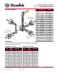
2. Weld end type valves already have the body bolts
loosen prior to shipment. Remove all the body bolts
(#19) and place them in a safe place.
3. Remove each end caps (#2) from the body (#1)
and carefully remove the soft parts (seats #4 and
gaskets #5 from each of the end caps) and place
them in a safe place.
4. Weld the pipe stub to each of the end caps. When
stub and the end cap has cooled down, clean both
end caps and stub body surface.
5. Replace the soft parts (seats #4 and gaskets #5)
into its original position. Replace all the bolts (#19)
and tighten slightly. This operation is very important
to keep body and end caps perfectly parallel, thus,
preventing distortion of the end caps.
6. Tighten body bolts evenly according to the body
bolt torque chart on next page.
7. Check the valve for proper operation.
Flow Direction