User Manual CF2002/CF3102 Printer
Welcome Thank you very much for your purchasing of the CF2002/CF3102 Printer. This user manual explains how to operate the printer and replenish its supplies. It also gives some troubleshooting tips as well as general precautions to be observed when operating the printer. To ensure the best performance and effective use of your printer, read this manual carefully until you familiarize yourself thoroughly with the printer’s operation and features.
Contents Contents 1 2 ii Introduction 1.1 Safety Information ........................................................................ 1-1 Warning and Precaution Symbols .................................................. 1-1 Meaning of Symbols ....................................................................... 1-1 WARNING ...................................................................................... 1-2 CAUTION .................................................................................
Contents 3 4 Before Making Prints 3.1 Components and Their Functions...............................................3-1 3.2 Parts Names and Their Functions ...............................................3-4 Outside of Printer ............................................................................3-4 Inside of Printer ...............................................................................3-6 Supplies and Parts ..........................................................................
Contents 5 6 Printer Panel Messages 5.1 Message List ................................................................................. 5-1 5.2 When the Message “No xxxx toner Please change” Appears ......................................................................................... 5-4 Messages and Actions ................................................................... 5-4 To replace the toner cartridge ........................................................ 5-5 5.
Contents 8 9 7.2 Care of the Printer.........................................................................7-8 Cleaning ..........................................................................................7-8 Housing cover .................................................................................7-8 Printer panel....................................................................................7-8 Paper take-up roller........................................................................
Contents vi CF2002/CF3102
1.1 Safety Information 1 Introduction 1.1 Safety Information This section contains detailed instructions on the operation and maintenance of this machine. To achieve optimum utility of this device, all operators should carefully read and follow the instructions in this manual. Please keep this manual in a handy place near the machine. ver.06 Please read the next section before using this device. It contains important information related to user safety and preventing equipment problems.
1.1 Safety Information Chapter 1 1 WARNING Introduction • Do not modify this product, as a fire, electrical shock, or breakdown could result. If the product employs a laser, the laser beam source could cause blindness. • Do not attempt to remove the covers and panels which have been fixed to the product. Some products have a high-voltage part or a laser beam source inside that could cause an electrical shock or blindness. • Use only the power cord supplied in the package.
Connect the power cord to an electrical outlet that is equipped with a grounding terminal. CAUTION • Do not use flammable sprays, liquids, or gases near this product, as a fire could result. • Do not leave a toner unit or drum unit in a place within easy reach of children. Licking or ingesting any of these things could injure your health. • Do not let any object plug the ventilation holes of this product. Heat could accumulate inside the product, resulting in a fire or malfunction.
1.1 Safety Information Precautions for Routine Use • Do not store toner units, PC drum units, and other supplies and consumables in a place subject to direct sunlight and high temperature and humidity, as poor image quality and malfunction could result. • Do not attempt to replace the toner unit and PC drum unit in a place exposed to direct sunlight. If the PC drum is exposed to intense light, poor image quality could result. • Do not unpack a toner unit or PC drum unit until the very time of use.
1 CE Marking (Declaration of Conformity) for Users of the European Union (EU) This product complies with the following EU directives: 89/336/EEC, 73/23/EEC and 93/68/EEC directives. Chapter 1 1.1 Safety Information For Users in countries not subject to Class B regulations WARNING This is a Class A product. In a domestic environment this product may cause radio interference in which case the user may be required to take adequate measures.
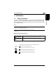
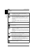
1.2 Explanation of Manual Conventions Introduction Chapter 1 1 1.2 Explanation of Manual Conventions The marks and text formats used in this manual are described below. WARNING Failure to observe instructions highlighted in this manner may result in fatal or critical injuries. ➜ Observe all warnings in order to ensure safe use of the printer. CAUTION Failure to observe instructions highlighted in this manner may result in serious injuries or property damage.
1.3 1 Chapter 1 1.3 Explanation of Basic Concepts Explanation of Basic Concepts The use of words and symbols in this manual are explained below. During printing, paper is supplied from the right side of the printer and fed into the output tray on top or the output option at the left with the printed surface of the page facing down. The paper feed direction is shown by the arrows in the diagram below.
Introduction Chapter 1 1 1.3 Explanation of Basic Concepts “Width” and “Length” Whenever paper dimensions are mentioned in this manual, the first value always refers to the width of the paper (shown as “Y” in the illustration) and the second to the length (shown as “X”). Paper Orientation Lengthwise If the width (Y) of the paper is shorter than the length (X), the paper has a vertical or portrait orientation, indicated by “L”.
1.4 Energy Star® Chapter 1 Energy Star® Introduction 1.4 1 As an ENERGY STAR® Partner, we have determined that this machine meets the ENERGY STAR® Guidelines for energy efficiency. What is an ENERGY STAR® Product? An ENERGY STAR® product has a special feature that allows it to automatically switch to a “low-power mode” after a period of inactivity. An ENERGY STAR® product uses energy more efficiently, saves you money on utility bills and helps protect the environment. 1.
1.
2.1 Installation Precautions 2 2 Precautions Installation Precautions Installation Site To ensure utmost safety and prevent possible malfunctions, install the printer in a location that meets the following requirements. - A location away from curtains, etc.
2.1 Installation Precautions 2 Space Requirements 72-1/2 (1,839) 50 (1,271) 11-1/4 (283) 21-1/4 (540) 56 (1,420) 30-3/4 (780) 4 (100) 38-1/4 (973) 36-3/4 (933) 11-1/4 (285) Unit: inch (mm) 72-1/2 (1,839) 50 (1,271) 56 (1,420) 21-1/4 4 (540) 30-3/4 (780) (100) 11-1/4 (283) 45 (1,143) 42 (1,066) 11-1/4 (285) 45 (1,143) Precautions Chapter 2 To ensure easy printer operation, supply replacement, and maintenance, adhere to the recommended space requirements detailed below.
2.2 Operation Precautions 2.2 2 Operation Precautions The environmental requirements for correct operation of the printer are as follows. Temperature: 50°F (10°C) to 86°F (30°C) with fluctuations of no more than 50°F (10°C) within an hour Humidity: 10% to 80% with fluctuations of no more than 20% within an hour Chapter 2 Operating environment To ensure the optimum performance of the printer, follow the precautions listed below.
2.2 Operation Precautions 2 Precautions Chapter 2 CAUTION If the ventilation duct at the top of the printer becomes blocked, the inside of the printer will accumulate heat, resulting in a malfunction or fire. ➜ Do not place any objects over the ventilation duct. CAUTION The area around the fusing unit is extremely hot. ➜ Be careful not to touch any parts around the fusing unit, other than those indicated in this manual, in order to reduce the risk of burns.
2.2 Operation Precautions 2 ➜ If your hands become soiled with toner, immediately wash them with soap and water. ➜ If toner gets in your eyes, immediately flush them with water, and then seek professional medical advice. Storage of prints ✚ Prints that are to be kept for a long time should be kept where they are not exposed to light in order to prevent them from fading. - Adhesive that contains solvent (e.g., spray glue) may dissolve the toner on prints.
2.
3.1 Components and Their Functions 3 3 Before Making Prints 3.1 Components and Their Functions 1 5 3 4 No. Part Name Description 1 Printer Prints the print data transmitted from the printer controller Referred to as the printer throughout the manual. 2 Printer Controller CN3102e For more details, refer to the manual of the printer controller. • Since this equipment is attached to the back of the printer, it is not shown in the above illustration.
3.1 Components and Their Functions 3 7 Before Making Prints Chapter 3 10 8 9 No. Part Name Description 7 Duplex Unit AD-14 (optional) Turns over prints, allowing double-sided prints to be made automatically. • If a printer controller (CN3102e) and the duplex unit are installed on the printer, the memory must be expanded. If the expanded memory is not installed, automatic double-sided printing cannot be performed.
3.1 Components and Their Functions Part Name Description 11 Punch KIT PK-4 (optional)* Allows the hole-punching function to be used if installed onto finisher FN-8 12 Memory M256-2 (USA, Canada: standard, others: optional) Increases the memory of the printer to 512 MB (256 MB standard memory + 256 MB expanded memory) By expanding the memory, the number of pages that can be stored in the memory can be increased. (Refer to Supplemental Table 1.
3.2 Parts Names and Their Functions 3 3.
3.2 Parts Names and Their Functions Part Name Description Right-side door Opened when clearing misfeeds (See p. 5-18 and p. 5-22.) 2 Manual bypass tray Used for manual feeding of paper The paper is fed one sheet at a time. Special paper can be loaded. (See p. 4-18.) 3 Power switch Used to turn the printer on and off (See p. 3-15.) 4 Lower right-side door Opened when clearing misfeeds (See p. 5-20.) 5 2nd drawer Holds up to 500 sheets of paper The paper size can be adjusted freely. (See p.
3.2 Parts Names and Their Functions 3 Inside of Printer 6 Before Making Prints Chapter 3 1 5 4 3 No. 3-6 Part Name 2 Description 1 Upper right-side door Opened when replacing the fusing unit or clearing misfeeds (See p. 5-24.
3.2 Parts Names and Their Functions 3 Supplies and Parts 2 3 5 7 No. 6 9 8 Part Name Before Making Prints 4 10 Description 1 Toner Cartridge There are four toner cartridges: cyan (C), magenta (M), yellow (Y) and black (BK). The combination of the four toners generates full-color images.
3.2 Parts Names and Their Functions 3 Options 7 8 9 10 1 6 Before Making Prints Chapter 3 5 4 2 3 Duplex Unit (AD-14) No. 1 Part Name Duplex unit door Description Opened when clearing a paper misfeed within the duplex unit Paper Feed Unit (PF-118) No. Part Name 2 3rd drawer 3 4th drawer Description Holds up to 500 sheets of paper As many as two units can be installed. The paper size can be adjusted freely. (See p. 4-15) Finisher (FN-8) No.
3.2 Parts Names and Their Functions 15 3 16 14 17 Chapter 3 13 Before Making Prints 12 11 Large Capacity Cabinet (PF-121) No. 11 Part Name 3rd drawer Description Holds up to 2,500 sheets of paper (See p. 4-17.) Finisher (FN-116) No.
3.3 Names of Printer Panel Parts and Their Functions 3 3.3 Names of Printer Panel Parts and Their Functions Names of Printer Panel Parts and Their Functions 8 1 Before Making Prints Chapter 3 2 3 4 5 6 7 No.
3.4 Selecting the Required Function 3.4 3 Selecting the Required Function In order to select functions, the [Functions] menu must be selected. The following functions can be selected from the [Functions] menu in the printer panel. To select a function 1 Check that “Info XXXX” appears in the Chapter 3 display, and then press the [Menu] key in the printer panel. ✎ Before Making Prints Note “XXXX” indicates the name specified when the controller was set up.
3.4 Selecting the Required Function 3 [Functions] menu Submenu Before Making Prints Chapter 3 Resume Printing Shut Down Restart Server Shut Down System Reboot System Run Setup This command is used to enter the Setup mode of the printer controller. (For more details, refer to the manual included with the printer controller.) Run Diagnostics This command is used to run the diagnostic function. (For details, refer to the manual included with the printer controller.
3.4 Selecting the Required Function 3 To set the Engine Setup Items For example: Low-Power Mode 1 Select “Engine Setup” and press the Before Making Prints Chapter 3 [Set] key. 2 “Login Admin Mode” (login screen for the setting mode used by the technical representative) is displayed. Select “No” and press the [Set] key. 3 Press or until the “Low-Power Mode” appears and press the [Set] key.
3.4 Selecting the Required Function 3 4 Select “On” or “Off” using or and Before Making Prints Chapter 3 press the [Set] key. 5 If “On” is selected, specify the length of time until the printer auotmatically enters the Low-Power Mode. 6 Press the [Set] key.
3.5 Turning the Printer On and Off 3.5 3 Turning the Printer On and Off To turn on the printer Set the power switch to “1”. To turn the printer off ➜ Set the power switch to “2”. ✎ Note Do not turn off the printer while it is printing, otherwise a paper misfeed may occur. Make sure that all print operations are finished before turning off the printer. ✎ Note If the printer is not used for a while, it automatically enters Energy Saver mode.
3.6 Turning the Printer Controller On and Off 3 3.6 Turning the Printer Controller On and Off To turn on the printer controller Set the power switch to “1”. Before Making Prints Chapter 3 ➜ After the printer controller is turned on, the controller is initialized. After the controller has finished warming up, the Ready light lights up in green and “Info XXXX” appears in the display.
3.6 Turning the Printer Controller On and Off 3 2 Press or until “Functions Shut Down” Chapter 3 appears, and then press the [Set] key. 3 Press once to display “Shut Down Before Making Prints System”, and then press the [Set] key to begin shutting down the system. 4 When the system has finished shutting down, “Safe to power off the system” appears. 5 Set the power switch of the printer controller to “2” to turn off the printer controller.
3.7 Total Counter 3 3.7 Total Counter The total counter can be printed out by following the procedure below. To print the total counter 1 Check that “Info XXXX” appears in the Before Making Prints Chapter 3 display, and then press the [Menu] key in the printer panel. 2 Press or until “Function Print Pages” appears, and then press the [Set] key. 3 Press or until “Functions Total Counter” appears, and then press the [Set] key.
3.7 Total Counter 3 4 The meter counter is printed out. Before Making Prints Chapter 3 (Refer to page 4-7 for Loading Paper.
3.8 Unit Check 3 3.8 Unit Check The life counter for the units can be printed out by following the procedure below. 1 Check that “Info XXXX” appears in the Before Making Prints Chapter 3 display, and then press the [Menu] key in the printer panel. 2 Press or until “Function Print Pages” appears, and then press the [Set] key. 3 Press or until “Functions Unit Check” appears, and then press the [Set] key.
3.8 Unit Check 3 4 The life counter is printed out. (Refer to Before Making Prints Chapter 3 page 4-7 for Loading Paper.
3.
4.1 Paper Specifications 4 4 Loading Paper 4.1 Paper Specifications Use paper that meets the following specifications. Paper Type Plain Paper Thick Paper 1 Thick Paper 2 Thick Paper 3 Weight (lbs.) 17 lbs. to 24 lbs. 24-1/4 lbs. to 40 lbs. 40-1/4 lbs. to 55-1/2 lbs. 55-3/4 lbs. to 68 lbs.
4.1 Paper Specifications 4 Paper Sizes Non-standard paper: Paper Source Paper Width Paper Length Manual bypass tray 3-9/16 in. to 12-1/4 in. (90 mm to 311 mm) 5-1/2 in. to 18 in. (140 mm to 457 mm) 1st drawer 2nd drawer — — — — Paper feed unit*1 Large capacity cabinet*1 Standard paper: 12.25 × 18 L (A3 Wide L) Loading Paper Chapter 4 Paper Size Ledger L (11 in. × 17 in. L) (A3 L) 11 × 14 L (B4 L) Legal L (A4 L) Paper Source, Etc.
4.1 Paper Specifications Paper Size 4 Executive C (A5 C) Executive L 4×6L Thick Paper (A6 Card Thick Paper) FLS. L (8 in. × 13 in. L) (B6 L) Paper Source, Etc. Manual bypass tray 2 2 2 2 1st drawer 2 2 2 2 2nd drawer 2 2 2 — Paper feed unit*1 — — — — Large capacity cabinet*1 — — — — Paper Capacity Paper Source, Etc.
4.1 Paper Specifications 4 ✎ Note The following types of paper should not be used, otherwise decreased print quality or paper misfeeds may occur.
4.2 Print Area 4.2 4 Print Area Any part of the image within the area indicated below is not printed. A margin 0.2 inch (5 mm) from the leading edge of the paper (A) A margin 0.2 inch (5 mm) from the trailing edge of the paper (B) A margin 0.2 inch (5 mm) on both sides of the paper (C) B A C 4.3 A: 0.2 inch (5 mm) B: 0.2 inch (5 mm) C: 0.2 inch (5 mm) Loading Paper C Chapter 4 Paper output direction Paper Storage Observe the following precautions when storing the paper.
4.4 Automatically Selecting the Paper Source 4 4.4 Automatically Selecting the Paper Source If the selected paper drawer runs out of paper while a print job is being made and a different paper drawer is loaded with paper meeting the following conditions, the other paper drawer is automatically selected so printing can continue. If the optional large capacity cabinet is installed, a maximum of 3,250 prints (with Letter C or A4 C paper) can be made continuously.
4.5 Loading Paper 4.5 4 Loading Paper Loading Paper Into the 1st Drawer 1 Pull out the paper drawer for the 1st drawer. Paper take-up roller 2 Press down on the paper-lifting plate until it locks into place. ✎ Chapter 4 Note Be careful not to touch the surface of the paper take-up roller with your hands. 3 Slide the lateral guides to fit the size of paper to be loaded.
4.5 Loading Paper 4 5 Load the paper into the drawer so that the side of the paper to be printed onto (the side facing up when the package was unwrapped) faces up. 6 When making manual double-sided prints, load the paper so that the second side (the blank side) faces up. ✎ Chapter 4 Note If the paper is curled, flatten it before loading it. Do not load so much paper that the top of the stack is higher than the Ä mark. Do not load more than 21 sheets of special paper.
4.5 Loading Paper 4 ✎ Tip When loading 4 × 6 L (A6) cards, load them with the shorter side as the leading edge, as shown. ✎ Chapter 4 Note Do not load 4 × 6 L (A6) cards crosswise, as shown. Loading Paper ✎ Tip After pressing down the envelopes to make sure that all air is removed and making sure that the folds of the flaps are firmly pressed, load the envelopes with the shorter side as the leading edge and with the side to be printed on facing down, as shown in the illustration.
4.5 Loading Paper 4 ✎ Chapter 4 Note Do not load envelopes crosswise, as shown. Loading Paper ✎ Tip When loading overhead projector transparencies, load them with the longer side as the leading edge, as shown. ✎ Note Do not load overhead projector transparencies lengthwise.
4.5 Loading Paper 4 7 If paper of a non-standard size has been loaded, slide the lateral guides against the edges of the loaded paper. 8 Close the paper drawer. 9 Turn the media type selection dial to the setting for the type of paper loaded.
4.5 Loading Paper 4 Setting the Paper Size for the 1st Drawer 1 Check that “Info XXXX” appears in the Loading Paper Chapter 4 display, and then press the [Menu] key in the printer panel. 2 Press or until “Engine Setup” appears, and then press the [Set] key. 3 “Login Admin Mode” (login screen for the setting mode used by the technical representative) is displayed. Select “No” and press the [Set] key.
4.5 Loading Paper 4 4 Check that “Tray 1 Setup” appears in the display window and press the [Set] key. 5 Press or and select either Auto, Inch, or Loading Paper Chapter 4 Metric and press the [Set] key. 6 Press or until the desired paper size appears, and then press the [Set] key.
4.
4.5 Loading Paper 4 Loading Paper Into the 2nd Drawer or a Paper Feed Unit 1 Pull out the paper drawer. 2 Press down on the paper-lifting Paper take-up roller plate until it locks into place. ✎ Note Be careful not to touch the surface of the paper take-up roller with your hands. Chapter 4 3 Remove the trailing-edge guide, and then re-install it for the size of paper to be loaded. Loading Paper 3 4 4 Slide the lateral guides to fit the size of paper to be loaded.
4.5 Loading Paper 4 5 Load the paper into the drawer so that the side of the paper to be printed onto (the side facing up when the package was unwrapped) faces up. ✎ Note If the paper is curled, flatten it before loading it. Do not load so much paper that the top of the stack is higher than the Ä mark. Loading Paper Chapter 4 Paper other than plain paper cannot be fed from the 2nd drawer or optional paper feed units.
4.5 Loading Paper 4 Loading Paper Into the Large Capacity Cabinet 1 Pull out the paper drawer. 2 Load paper into the right side of the drawer so that the front side of the paper (the side facing up when the package was unwrapped) faces up. ✎ Note If the paper is curled, flatten it before loading it. The paper guide in the large capacity cabinet has been installed for Letter C (A4 C)-size paper. To use B5 C-size paper, consult your authorized service representative (for metric areas only).
4.5 Loading Paper 4 Loading Paper Into the Manual Bypass Tray Paper can be fed manually through the manual bypass tray if you wish to print onto paper that is not loaded into a drawer, or if you wish to print onto special paper. 1 Open the manual bypass tray. Loading Paper Chapter 4 2 Prepare one sheet of the paper. 3 Load the paper into the manual bypass tray so that the front side of the paper (the side facing up when the package was unwrapped) faces down.
4.5 Loading Paper 4 ✎ Tip When loading 4 × 6 L (A6) cards, load them with the shorter side as the leading edge, as shown. ✎ Chapter 4 Note Do not load 4 × 6 L (A6) cards crosswise, as shown. Loading Paper ✎ Tip Before loading envelopes, press them down to make sure that all air is removed, and make sure that the folds of the flaps are firmly pressed, otherwise the envelopes may become wrinkled or a paper misfeed may occur.
4.5 Loading Paper 4 ✎ Loading Paper Chapter 4 Note Do not load envelopes crosswise, as shown. ✎ Tip When loading Overhead Projector transparencies, load them with the longer side as the leading edge, as shown. ✎ Note Do not load Overhead Projector transparencies lengthwise, as shown.
4.5 Loading Paper 4 4 Adjust the paper guides to fit the size of paper that is loaded. 5 Lightly slide the paper into the feed slot as much as possible so that the edge of the paper is fed into the printer. ❍ Feed only one sheet of paper at a time. Loading Paper Chapter 4 6 Printing can begin.
4.
5.1 Message List 5 5 Printer Panel Messages 5.1 Message List When a message appears in the printer panel display, refer to the section for details about the message and the action to be taken. ✎ Cause Action Check power of DT unit Power is not being supplied to the DT-105. Check that power is supplied to the DT-105. Cover open at xx The indicated cover is open. Press Ä once, check which cover is open, and then close it. • front p. 3-5, #7 • right side p. 3-5, #1 • left side p.
5.1 Message List Printer Panel Messages Chapter 5 5 Message Cause Action Low-power mode The printer has entered Energy Saver mode. • To cancel Energy Saver mode, send a print job, or open and close a cover. • To change the time for the printer to enter Energy Saver mode, see “To set the Engine Setup Items” on page 3-13. Near trouble ## / ## Some malfunction occurred in the printer. Contact your technical representative and inform them of the error code. (See p.
5.1 Message List 5 Cause Action xxxx toner nearly empty The toner for the indicated color will soon be empty. Prepare to replace the toner cartridge with a new one. xxxx unit near life limit The indicated unit will soon reach the end of its life. Replace the indicated unit. (See p. 5-45.) xxxx unit not set The indicated unit is not installed. Install the indicated unit.
5.2 When the Message “No xxxx toner Please change” Appears 5 5.2 When the Message “No xxxx toner Please change” Appears Messages and Actions The toner for the indicated color is empty. Replace the toner cartridge with a new one as described in the maintenance agreement. CAUTION Be careful not to spill toner inside the printer or get toner on your clothes or hands. ➜ If your hands become soiled with toner, immediately wash them with soap and water.
5.2 When the Message “No xxxx toner Please change” Appears 5 To replace the toner cartridge The procedure for replacing any of the toner cartridges (yellow (Y), magenta (M), cyan (C) or black (Bk)) is the same. The following procedure describes the replacement of the yellow toner cartridge as an example. ✎ Note Be careful since the installation location of toner cartridges for other colors is different.
5.2 When the Message “No xxxx toner Please change” Appears 5 3 Prepare the new toner cartridge. ❍ Make sure that the color of the toner cartridge is the same color as the lever. ✎ Note Do not install the toner cartridge of a color different than the one that was removed, otherwise the machine may be damaged. 4 Shake the new toner cartridge well. ✎ Printer Panel Messages Chapter 5 Note The toner within the toner cartridge may have become compacted.
5.2 When the Message “No xxxx toner Please change” Appears 5 6 Position the toner cartridge as shown, and then insert it into its compartment. 7 Turn the lever clockwise. ✎ Printer Panel Messages Chapter 5 Note Make sure that the lever is fully turned, as shown, otherwise the front door cannot be closed. 8 Slowly pull out the chargercleaning tool as far as possible, and then slowly push in the charger-cleaning tool as much as possible. Repeat this step three times.
5.3 When the Message “No Staples” Appears 5 5.3 When the Message “No Staples” Appears When finisher FN-116 or FN-8 is installed and is about to run out of staples, the message shown above appears. Follow the procedure below to replace the staple cartridge. ✎ Note Be sure to replace the staple cartridge only after the message appears, otherwise the machine may be damaged. To replace the staple cartridge for FN-116 1 Slide the finisher away from the Printer Panel Messages Chapter 5 printer.
5.3 When the Message “No Staples” Appears 5 3 Pull the staple holder out toward you. Stapler 4 Remove the empty staple Chapter 5 cartridge. Printer Panel Messages 5 Insert the new staple cartridge into the staple holder, and then carefully pull out the stopper.
5.3 When the Message “No Staples” Appears 5 6 Insert the refilled staple holder until it locks into place. 7 Slide the finisher back against the Printer Panel Messages Chapter 5 printer.
5.3 When the Message “No Staples” Appears 5 To replace the staple cartridge for FN-8 ✎ Note Be sure to replace the staple cartridge only after the message appears, otherwise the machine may be damaged. Chapter 5 1 Open the front door of the finisher. 2 Turn misfeed-clearing dial clockwise until the removal indicator is completely blue. If the dial is turned too far, turn it counterclockwise to adjust it.
5.3 When the Message “No Staples” Appears 5 3 Slowly pull out the stapler unit as far as possible. 4 Turn dial clockwise until the staple cartridge moves to a position from where it can be removed. If the dial is turned too far, turn it counterclockwise to adjust it. Printer Panel Messages Chapter 5 ❍ 5 Grasp both sides of the staple cartridge, lift up the staple cartridge, and then pull it out.
5.3 When the Message “No Staples” Appears 5 6 Press the button marked “PUSH” on the side of the staple cartridge. The staple case is released. PU SH Printer Panel Messages Chapter 5 7 Pull up the staple case. 8 Remove the paper holder from the staple case.
5.3 When the Message “No Staples” Appears 5 9 Refill the staple case with staples. ❍ Fully insert the staple case as far as possible. Printer Panel Messages Chapter 5 10 Press the staple case down. 11 Peel off the tape from the staples.
5.3 When the Message “No Staples” Appears 5 12 Insert the staple cartridge, making sure the tabs on the cartridge slide along the rails in the compartment. 13 Fully insert the staple cartridge so that it locks into place. ❍ Check that the staple cartridge is firmly installed. Chapter 5 14 Carefully move the stapler unit back into its original position. Printer Panel Messages 15 Close the front door.
5 5.4 5.4 When the Message “Paper jam at Jx” Appears When the Message “Paper jam at Jx” Appears If a paper misfeed or a staple jam occurs during printing, the message shown below appears. Printer Panel Messages Chapter 5 Press ▼ once and check where the paper misfeed occured. Follow the procedure below to clear the misfed paper or the jammed staples.
5.4 When the Message “Paper jam at Jx” Appears 5 Codes and Paper Misfeed Locations Code Jammed position Code Printer Panel Messages Chapter 5 Check the label affixed to the front door for instructions on the location where the paper misfeed occurred. Jammed position JA 1st drawer (p. 5-20) JI printer, upper right-side door (p. 5-24) JB 2nd drawer (p. 5-20) JJ finisher, horizontal transport unit cover (p. 5-27, p. 5-31) JC 3rd drawer (p. 5-20) large capacity cabinet (p.
5.4 When the Message “Paper jam at Jx” Appears 5 To clear a paper misfeed in the manual bypass tray 1 Pull up the lock release lever to open the right-side door. Printer Panel Messages Chapter 5 CAUTION Decreased print quality may result if the surface of the image transfer belt or the image transfer roller is touched. ➜ Be careful not to touch the Image transfer belt surface of the image transfer belt or the image transfer roller. Image transfer roller 2 Carefully pull out the paper.
5.4 When the Message “Paper jam at Jx” Appears 5 To clear a paper misfeed in the duplex unit 1 Open the duplex unit door. 2 Carefully pull out the paper. Printer Panel Messages Chapter 5 3 Close the duplex unit door.
5.4 When the Message “Paper jam at Jx” Appears 5 To clear a paper misfeed in the paper drawer 1 Open the lower right-side door of the paper drawer begin used. 2 Turn the green wheels to feed the Printer Panel Messages Chapter 5 paper so that it can be easily removed. 3 Carefully pull out the paper. 4 Close the lower right-side door. 5 Pull out the paper drawer, and then remove any misfed paper. 6 Close the paper drawer.
5.4 When the Message “Paper jam at Jx” Appears 5 To clear a paper misfeed in the large capacity cabinet 1 Open the right-side door of the large capacity cabinet. 2 Turn the green dial in the direction of the arrow to feed out the paper. 4 Close the right-side door of the large capacity cabinet. 5 Pull out the paper drawer of the large capacity cabinet, and then remove any misfed paper. 6 Close the paper drawer of the large capacity cabinet.
5.4 When the Message “Paper jam at Jx” Appears 5 To clear a paper misfeed inside the printer 1 Pull out the paper drawer being used, and then remove any paper remaining in the drawer. 2 Load the paper in the drawer again, and then close the drawer. ✎ Note Be careful not to touch the surface of the paper take-up roller with your hands. 3 Pull up the lock release lever to Printer Panel Messages Chapter 5 open the right-side door.
5.4 When the Message “Paper jam at Jx” Appears 5 5 Pull out any paper caught in the image transfer roller section. CAUTION Image transfer roller ✎ Note If the paper is caught as described below, contact your technical representative. The paper is wrapped around the roller in the image transfer roller. The paper is folded or shredded by the roller in the image transfer roller. The paper that was removed tore and remains in the fusing unit.
5.4 When the Message “Paper jam at Jx” Appears 5 6 Pull out any paper caught in the fusing unit. 7 Grasp the upper right-side door as shown, and then carefully open the door completely while making sure to support it. Printer Panel Messages Chapter 5 ✎ Note Be sure to support the door while carefully opening it, otherwise it may be damaged. 8 While moving the green lever on the inside of the upper right-side door in the direction of the arrow, carefully pull out the paper.
5.4 When the Message “Paper jam at Jx” Appears 5 CAUTION The area around the fusing unit is extremely hot. ➜Touching anything other than the indicated parts may result in burns. If you get burnt, immediately cool the skin under cold water, and then seek professional medical attention. 9 Grasp the tab on the left end of the Printer Panel Messages Chapter 5 fusing unit cover, and then swing the cover toward you to open it. 10 Pull out any paper caught in the fusing unit.
5.4 When the Message “Paper jam at Jx” Appears 5 CAUTION The area around the fusing unit is extremely hot. ➜Touching anything other than the indicated levers and dials may result in burns. If you get burnt, immediately cool the skin under cold water, and then seek professional medical attention. ✎ Chapter 5 Note If the paper is caught as described below, contact your technical representative. The paper is wrapped around the fusing unit. The paper is folded or shredded by the fusing unit.
5.4 When the Message “Paper jam at Jx” Appears 5 To clear a paper misfeed in finisher FN-116 1 Slide the finisher away from the printer. 2 Open the horizontal transport unit cover, and then remove any paper. Chapter 5 3 Close the horizontal transport unit Printer Panel Messages cover. 4 Open front door FN4.
5.4 When the Message “Paper jam at Jx” Appears 5 5 Turn knobs FN5 clockwise at the same time. 6 While holding the misfeed-clearing Printer Panel Messages Chapter 5 guide FN7 open, pull out any paper. FN7 7 When the paper can be seen from the print output tray, turn knobs FN5 counterclockwise at the same time to feed out any paper. 8 Close front door FN4.
5.4 When the Message “Paper jam at Jx” Appears 5 9 Open upper cover FN1. CAUTION Metallic parts on the inside of upper cover FN1 are very hot. ➜ Touching anything other than the paper within the area around the fusing unit may result in burns. 10 While holding misfeed-clearing Printer Panel Messages Chapter 5 guide FN2 open, pull out any paper. 11 While holding misfeed-clearing guide FN3 open, pull out any paper. 12 Close upper cover FN1. ❍ If the Option tray is not installed, skip to step 16.
5.4 When the Message “Paper jam at Jx” Appears 5 13 If the Option tray is installed: Open the Option tray. 14 Remove any misfed paper. Chapter 5 15 Close the Option tray. Printer Panel Messages 16 While holding misfeed-clearing guide FN6 open, pull out any paper. 17 Slide the finisher back against the printer.
5.4 When the Message “Paper jam at Jx” Appears 5 To clear a paper misfeed in finisher FN-8 1 Slide the finisher away from the printer. 2 Open the cover of the horizontal transport unit. 3 Remove any paper, and then Printer Panel Messages Chapter 5 close the cover of the horizontal transport unit. 4 Open the front door of the finisher.
5.4 When the Message “Paper jam at Jx” Appears 5 5 Turn misfeed-clearing dial clockwise until the removal indicator is completely blue. ❍ If the dial is turned too far, turn it counterclockwise to adjust it. ✎ Note Be sure to perform these steps. If the paper is pulled out with too much force without performing these steps, the finisher may be damaged. 6 Open the upper door of the Printer Panel Messages Chapter 5 finisher, and then pull out any paper in the feed section. 7 Close the upper door.
5.4 When the Message “Paper jam at Jx” Appears 5 9 Open the feed guide for the finisher, and then remove any paper. 10 Open the transport guide, and then pull out any paper in the transport section. ✎ Pulling out the paper with too much force may damage the folding unit. If the paper cannot be pulled out easily, turn the misfeed-clearing dial in the folding section as described in the following step, and then pull out the paper.
5.4 When the Message “Paper jam at Jx” Appears 5 12 Close the front door of the finisher. ✎ Note Be careful that your fingers are not pinched when the front door is closed. Printer Panel Messages Chapter 5 13 Slide the finisher back against the printer.
5.4 When the Message “Paper jam at Jx” Appears 5 To clear jammed staples in FN-116 1 Slide the finisher away from the printer. 2 Turn the dial to the left in order to Printer Panel Messages Chapter 5 position the stapler at the center. 3 Pull the staple holder out toward you.
5.4 When the Message “Paper jam at Jx” Appears 5 4 Push the staple holder guide up, and then pull out one sheet of staples. 5 Move the guide back to its original position. 6 Insert the staple holder until it Printer Panel Messages Chapter 5 locks into place. 7 Slide the finisher back against the printer. ✎ Note If stapling still cannot be performed, even after performing the above procedure, contact your technical representative.
5.4 When the Message “Paper jam at Jx” Appears 5 To clear jammed staples in FN-8 1 Slide the finisher away from the printer. 2 Open the cover of the horizontal transport unit. 3 Remove any paper, and then Printer Panel Messages Chapter 5 close the cover of the horizontal transport unit. 4 Open the feed guide for the finisher, and then remove any paper.
5.4 When the Message “Paper jam at Jx” Appears 5 5 Open the front door of the finisher. 6 Turn misfeed-clearing dial clockwise until the removal indicator is completely blue. ❍ ✎ Chapter 5 Printer Panel Messages If the dial is turned too far, turn it counterclockwise to adjust it. Note Be sure to perform these steps. If the paper is pulled out with too much force without performing these steps, the finisher may be damaged. 7 Pull out any paper fed into the output tray.
5.4 When the Message “Paper jam at Jx” Appears 5 8 Open the transport guide, and then pull out any paper in the transport section. ✎ Note If the paper cannot easily be pulled out, stop trying to pull it out. Pulling out the paper with too much force may damage the folding unit. If the paper cannot be pulled out easily, turn the misfeed-clearing dial in the folding section as described in the following step, and then pull out the paper.
5.4 When the Message “Paper jam at Jx” Appears 5 11 Turn misfeed-clearing dial clockwise until the cartridge removal indicators are aligned. The staple cartridge moves to a position from where it can be removed. ❍ If the dial is turned too far, turn it counterclockwise to adjust it so the cartridge removal indicators are aligned. 12 Grasp both sides of the staple Printer Panel Messages Chapter 5 cartridge, lift up the staple cartridge, and then pull it out.
5.4 When the Message “Paper jam at Jx” Appears 5 14 Pull out toward you the two staples jammed at the end of the staple cartridge. ✎ Note Be sure to remove two staples, otherwise stapling cannot continue correctly. 15 Return the shutter of the staple cartridge to its original position. 16 Insert the staple cartridge, making Printer Panel Messages Chapter 5 sure the tabs on the cartridge slide along the rails in the compartment. 17 Fully insert the staple cartridge so that it locks into place.
5.5 When the Message “Punch dust full Please change” Appears 5 5.5 When the Message “Punch dust full Please change” Appears If the punch kit PK-4 is installed in the finisher FN-8, the above message will appear when the hole-punch waste container is full with punch scraps. To empty the hole-punch waste container Empty the hole-punch waste container, and then re-install it according to the following procedure. 1 Slide the finisher away from the Chapter 5 printer.
5.5 When the Message “Punch dust full Please change” Appears 5 3 Empty the container. 4 Insert the hole-punch waste container into its original position. 5 Slide the finisher back against the Printer Panel Messages Chapter 5 printer.
5 5.6 5.6 When the Message “Service Code Cxxxx” Appears When the Message “Service Code Cxxxx” Appears When the message shown below appears in the printer panel display, a malfunction has occurred within this printer. Printer Panel Messages Chapter 5 Press Äonce and check which error code is displayed. If this message appears, contact your technical representative and inform them of the error code that is indicated.
5.7 When the Message “xxxx unit near life limit” Appears 5.7 5 When the Message “xxxx unit near life limit” Appears ✎ Printer Panel Messages Note The display window only displays two lines of a message at one time. To view messages longer than two lines, press Ä to display the next line of the message. Chapter 5 When it is almost time to replace a unit within this printer, a message like the one shown below appears in the printer panel.
5 5.8 5.8 When the Message “Near trouble ## / ##” Appears When the Message “Near trouble ## / ##” Appears When the message shown below appears in the printer panel display, image stabilization and printing functions for the printer have become unstable. Printer Panel Messages Chapter 5 Press Äonce and check which error code is displayed. If this message appears, contact your technical representative and inform them of the error coad that is indicated.
6.1 Improving Print Quality 6 6 Troubleshooting 6.1 Improving Print Quality Symptom Cause Action The image is too light. The setting in the printer driver is not set properly. Adjust the setting in the printer driver to the desired level. The paper loaded in the tray is damp. Replace the old paper with fresh dry paper. p. 4-7 The toner will soon be empty. Replace the toner cartridge. p. 5-5 The imaging unit may be defective. Contact your tecnical representative.
6.1 Improving Print Quality 6 Symptom Cause Action Inconsistent image density. The imaging unit requires replacement. Contact your technical representative. The image transfer belt unit requires replacement. White lines. The imaging unit requires replacement. Contact your technical representative. The image transfer belt unit requires replacement. The printer’s internal paper path is dirty. Run several prints to flush out the debris. The imaging unit requires replacement.
6.1 Improving Print Quality Cause Action Black pages The imaging unit requires replacement. Contact your technical representative. Blank pages The imaging unit requires replacement. Contact your technical representative. Paper wrinkles during printing. The paper being used is not compatible with the printer. See “4.1 Paper Specifications” for compatible types of paper. p. 4-1 Paper is not loaded properly in the tray. See “4.5 Loading Paper”. p. 4-7 The fusing unit requires replacement.
6.
7.1 Specifications Chapter 7 7 7 Appendix 7.1 Specifications Appendix Printer CF2002/CF3102 Specification Type Desktop Platen Stationary Photo conductor OPC Printing system Dry-type electrophotographic method Developing system MTHG developing method Fusing system Belt-fixing Resolution Scanning: 600 dpi, Printing: 600 dpi × 1800 dpi equivalent Paper types Plain paper (17 to 24 lbs. or 64 to 90 g/m2), thick paper 1* (24-1/4 to 40 lbs.
7.1 Specifications Appendix Chapter 7 7 Specification Lost image Leading edge: 0.2 inch (5 mm) Trailing edge: 0.2 inch (5 mm) Rear edge: 0.2 inch (5 mm) Font edge: 0.2 inch (5 mm) First print (CF2002) Full color: Less than 14.1 seconds Black: Less than 7.9 seconds (for Letter C or A4 C paper loaded into the 1st drawer) First print (CF3102) Full color: Less than 9.9 seconds Black: Less than 7.
7.1 Specifications Duplex Unit AD-14 Specification Paper type Plain paper (17 to 24 lbs. or 64 to 90 g/m2) Paper size (For Inch) 12-1/4 × 18, 11 × 14 L, 8-1/2 × 14 L, 8-1/2 × 13 L, 8-1/2 × 11 L/C, 8 × 10⁻¹/2 L/C, 8 × 10 L/C, 7-1/2 × 10-1/2 L/C (For Metric) A3 Wide L, A3 L, B4 L, A4 L/C, B5 L/C Power requirements Supplied by printer Power consumption Less than 17 W Dimensions W: 5-1/2 in. (139 mm) D: 17-1/4 in. (440 mm) H: 14-1/4 in. (365 mm) Weight About 6-3/4 lbs (3.
7.1 Specifications Appendix Chapter 7 7 Large Capacity Cabinet PF-121 Specification Paper type Plain paper (17 to 24 lbs. or 64 to 90 g/m2) Paper size (For Inch) Letter C (8-1/2 × 11 L) (For Metric) A4 C, B5 C Paper capacity 2,500 sheets (21-1/4 lbs. or 80 g/m2) Power requirements Supplied by printer Power consumption Less than 45 W Dimensions W: 21 in. (535 mm) D: 22-1/4 in. (568 mm) H: 11-1/4 in. (284 mm) Weight About 37-1/2 lbs. (17.
7.
7.1 Specifications Appendix Chapter 7 7 Finisher FN-116 Specification No. of bins Non-sort tray, Elevated tray Settings “Non-sort”, “Sort”, “Group” and “Staple” settings Paper type Non-sort tray: “Non-sort” setting: Plain paper (17 to 24 lbs. or 64 to 90 g/m2), Thick 1 (24-1/4 to 40 lbs. or 91 to 150 g/m2), Thick 2 (40-1/4 to 551/2 lbs. or 151 to 209 g/m2), Thick 3 (55-3/4 to 68 lbs.
7.1 Specifications Option Tray JS-100 Specification Setting Option Tray Paper type Plain paper (17 to 24 lbs. or 64 to 90 g/m2) Paper size (For Inch) Invoice L (5-1/2 × 8-1/2 L), Letter L/C (8-1/2 × 11 L/C), Executive L/C, 7-1/4 × 10-1/2 L/C, Legal L (8-1/2 × 14 L), Ledger L (11 × 17 L) (For Metric) A4 L/C, A3 L Paper capacity Letter C (A4 C): 100 sheets, Except Letter C (A4 C): 50 sheets Dimensions W: 13-1/2 in. (341 mm) D: 20-3/4 in. (527 mm) H: 5-3/4 in. (149 mm) Weight About 3-3/4 lbs. (1.
7.2 Care of the Printer Chapter 7 7 7.2 Care of the Printer Cleaning Appendix Set the power switch of the printer to “O” before cleaning it. Housing cover ➜ Clean the surface of the housing cover by wiping it with a soft cloth dampened with a mild household detergent. Printer panel ➜ Clean the printer panel by wiping it with a soft, dry cloth. ✎ Note Pressing too hard on the printer panel may damage them. In addition, never use mild household detergent or glass cleaner to clean the printer panel.
7 Chapter 7 7.2 Care of the Printer Paper take-up roller Clean the paper take-up roller by wiping it with a soft, dry cloth. Appendix ➜ Electrostatic charger If the electrostatic charger is dirty, streaks will appear though the prints. If this occurs, clean the charger according to the following procedure. 1 Open the front door. 2 Slowly pull out the chargercleaning tool as far as possible, and then slowly push in the charger-cleaning tool as much as possible. Repeat this step three times.
7.3 Consumables Appendix Chapter 7 7 7.3 Consumables In order to maintain the condition of this machine, the following consumables are needed. For best print quality, we recommend that the specified supplies be used. For information on or for purchasing supplies, contact your nearest technical representative. Paper In addition to plain paper, thick paper, 12.25 × 18L (A3 Wide) paper and overhead projector transparencies are also available.
7 Chapter 7 7.3 Consumables Staple Cartridges FN-116 Staples for staple binding Appendix 3,000 staples are provided in the staple cartridge. FN-8 Staples for staple binding 5,000 staples are provided in the staple cartridge.
7.
8.1 System Requirements 8 PageScope Light is a device control utility program provided by the HTTP server built into the printer controller. This utility can be used with a Web browser as an interface for remotely controlling the printer. 8.1 System Requirements The following items are required to use this utility. Using PageScope Light Computer Software Operating System Web Browser Windows 98/NT 4.0 Internet Explorer 4 or higher, Netscape Navigator 4 or higher Windows Me Internet Explorer 5.
8.2 Access 8 8.2 Access PageScope Light can be accessed directly from a Web browser. Using PageScope Light Chapter 8 1. Start the Web browser. 2. In the Address bar, enter the IP address of the printer controller as shown below. Then, press [Enter]. http:/// (Example) When the IP address of the printer controller is 192.168.0.10: http://192.168.0.10/ 3. The PageScope Light screen appears.
8.3 Screen Configuration The screen shown below is called the User Mode screen; all users can view this screen. By entering an appropriate password in the “Admin Password” box on the User Mode screen, you can enter the Administrator Mode screen. (See p. 8-5.) The configuration of the PageScope Light screen is shown below. ✎ Note Screen images shown in this manual may differ slightly from actual ones. In addition, specifications are subject to change without prior notice.
8.3 Screen Configuration Using PageScope Light Chapter 8 8 8-4 4 Tabs Selects the category of items to be displayed. • System • Print • Network (Administrator Mode only) For details on each tab, see the following sections. 5 Menus Selects the information or setup item to be displayed. The menus that appear vary depending on the tab selection. For details on each menu, see the following sections. 6 Information and Setting Details Displays the details of the selected menu.
8.3 Screen Configuration 8 Logging in Using the Administrator Mode 1 Enter the administrator password into the “Admin Password” box at the upper left corner of the screen. Using PageScope Light 2 Click [Log-in] to log in using the Administrator Mode. Chapter 8 By logging into PageScope Light in the Administrator Mode, you can configure or confirm the printer controller system. 3 To log out, click [Log-out]. ✎ Note Contact the printer administrator for the password.
8.4 User Mode 8 8.4 User Mode Using PageScope Light Chapter 8 System Tab On the [System] tab, information concerning the system configuration of the printer and settings are displayed. Summary This screen is the initial screen that appears when you access http:/// with your Web browser. You can also display the Summary screen by clicking the [Summary] menu on the [System] tab. The Summary screen shows the current printer system configuration and status.
8.4 User Mode 8 Detail Input Tray Using PageScope Light This screen appears when you click the [Input Tray]]sub-menu under the [Detail] menu. It shows the configuration of all the paper feed trays installed on the printer. Chapter 8 This screen appears when you click the [Detail] menu on the [System] tab. Clicking a sub-menu under the [Detail] menu displays information about the applicable unit.
8.4 User Mode 8 Output Tray Using PageScope Light Chapter 8 This screen appears when you click the [Output Tray] sub-menu under the [Detail] menu. It shows the configuration of all the output trays installed on the printer.
8.4 User Mode 8 Printer Hard Disk Using PageScope Light Chapter 8 This screen appears when you click the [Printer HDD] sub-menu under the [Detail] menu. It shows the status of the hard disk installed on the printer controller.
8 8.4 User Mode This screen appears when you click the [Consumables] sub-menu under the [Detail] menu.
8.4 User Mode 8 Counter Using PageScope Light Chapter 8 This screen appears when you click the [Counter] menu on the [System] tab. It shows various counter values that the printer manages.
8 8.4 User Mode This screen appears when you click the [Online Assistance] menu on the [System] tab. It shows information concerning product support. The information can be edited in the Administrator Mode. (See p. 8-21.
8.4 User Mode 8 Print Tab The [Print] tab is used to configure the printer controller. General Setting This screen appears when you click the [General Setting] sub-menu under the [Default Setting] menu. The screen is used to specify the default settings of the paper feed tray, duplex printing, and the number of copies. Input Tray: From the drop-down list, select the default paper feed tray.
8.4 User Mode 8 This screen appears when you click the [PCL Setting] sub-menu under the [Default Setting] menu. The screen is used to set default values for various PCL settings. If the page description language that the printer controller received is PCL, the settings of the job have precedence. Using PageScope Light Chapter 8 PCL Setting 8-14 Paper Size: From the drop-down list, select the default paper size. Orientation: From the drop-down list, select the default orientation of the paper.
8.4 User Mode 8 Using PageScope Light This screen appears when you click the [PostScript] Setting sub-menu under the [Default Setting] menu. The screen is used to set default values for various PostScript settings. If the page description language that the printer controller received is PostScript, the settings of the job have precedence.
8 8.4 User Mode This screen appears when you click the [Font Information] menu on the [Print] tab. It shows a list of PCL fonts and PostScript fonts that are built into the printer controller. PCL Font This screen appears when you click the [PCL Fonts] sub-menu under the [Font Information] menu. It shows a list of PCL fonts that are built into the printer controller.
8.4 User Mode 8 Using PageScope Light This screen appears when you click the [PostScript Fonts] sub-menu under the [Font Information] menu. It shows a list of PostScript fonts that are built into the printer controller.
8 8.4 User Mode Print Pages Using PageScope Light Chapter 8 This screen appears when you click the [Print Pages] menu on the [Print] tab. The screen is used to select the test page to be printed and execute the printing.
8.5 Administrator Mode 8.5 8 Administrator Mode System Tab On the [System] tab, information concerning the system configuration of the printer and settings are displayed. Preference This screen appears when you click the [Preference] menu on the [System] tab. The screen is used to specify settings concerning the screen display. Refresh Rate: Sets the refresh rate of PageScope Light. Settings: 30 to 7200 sec. Display Language: Sets the display language of PageScope Light.
8 8.5 Administrator Mode This screen appears when you click the [ROM Version] menu on the [System] tab. It shows the ROM version of the printer, the firmware version of the controller, and other information.
8.5 Administrator Mode 8 Online Assistance Using PageScope Light Chapter 8 This screen appears when you click the [Online Assistance] menu on the [System] tab. You can use the screen to enter information concerning product support.
8.5 Administrator Mode 8 This screen appears when you click the [Maintenance] menu on the [System] tab. You can use the screen to restart the printer controller or initialize the settings (reset to factory default settings). Restart This screen appears when you click the [Restart] sub-menu under the [Maintenance] menu. You can use the screen to restart the printer controller. Using PageScope Light Chapter 8 Maintenance Printer Controller/[Restart] button: 8-22 Restarts the printer controller.
8.5 Administrator Mode 8 Initialize Using PageScope Light Chapter 8 This screen appears when you click the [Initialize] sub-menu under the [Maintenance] menu. You can use the screen to initialize the printer controller settings (reset to factory default settings). Printer Controller/[Restore] button: CF2002/CF3102 Resets the printer controller settings to factory default. Click the [Restore] button to show a screen used to confirm whether to execute the initialization.
8.5 Administrator Mode 8 Print Tab The [Print] tab is used to configure the printer controller. This screen appears when you click the [Local Interface] menu on the [Print] tab. The screen is used to show or set information concerning the local port. Using PageScope Light Chapter 8 Local Interface 8-24 Parallel Interface: Displays the setting selected under “Enable Parallel Port” in the Setup mode of the printer controller.
8.5 Administrator Mode 8 Network Tab The [Network] tab shows settings concerning the printer controller network. Using PageScope Light This screen appears when you click the [Summary] menu on the [Network] tab. It shows a summary of the printer controller interface (TCP/IP settings).
8.
9.1 Index 9 9 Index 9.1 Index Numerics 1st drawer ............................................................................................3-5 2nd drawer Paper-empty indicator ......................................................3-5 3rd drawer ................................................................................... 3-8, 3-9 4th drawer ............................................................................................3-8 Index A Administration mode Network tab .................
9.1 Index 9 Finisher connector .............................................................................. 3-5 Front door ............................................................................ 3-5, 3-8, 3-9 Fusing unit .......................................................................................... 3-7 H Hard disk ............................................................................................. 3-3 Chapter 9 Horizontal transport unit cover ................................
9.1 Index 9 O Operation precautions .........................................................................2-3 Option tray ............................................................................3-1, 3-9, 7-7 Ozone filter ..........................................................................................3-7 P Administration mode ....................................................................8-19 Screen configuration ......................................................................
9.1 Index 9 Ready light .................................................................................. 3-10 Right/left keys .............................................................................. 3-10 Set key ........................................................................................ 3-10 Up/down keys .............................................................................. 3-10 Printer panel functions Chapter 9 Calibration ...................................................
9.1 Index 9 U Upper cover .........................................................................................3-9 Upper door ...........................................................................................3-8 Upper right-side door ...........................................................................3-6 User mode W Index Waste-toner bottle ...............................................................................3-7 Chapter 9 Print tab .......................................
9.
Copyright 2002 MINOLTA CO., LTD. The information contained in this manual is subject to change without notice to incorporate improvements made on the product or products the manual covers. 2002. 12 MINOLTA CO., LTD. 3-13, 2-chome, Azuchi-Machi, Chuo-ku, Osaka.