RPX900D INDUSTRIAL EVAPORATIVE AIR COOLERS Assembly Instructions Advanced natural cooling
RPX ASSEMBLY INSTRUCTIONS INDEX Description Index Important Notice/ Tools required Installing Fan Housing to Tank 1/5 Installing Top Channel Sealing Fan Housing to Tank 1/2 Sealing Fan Housing to Tank Bottom Prepare Motor and Controls 1/4 Fan Pulley Attachment Fit and Tension V Belts Fitting the Water Pumps Connecting the Water System Corner Pillar Installation Centre Rail Installation Top Rail Installation 1/2 Bottom Rail Installation Centre Pillar Installation Water Spreader Installation Distributor Cap I
RPX ASSEMBLY INSTRUCTIONS IMPORTANT NOTICE The assembly of evaporative air conditioning units has the potential to create Occupational Health and Safety issues for those involved. Assemblers are advised to ensure they are familiar with relevant State and Federal legislation, such as Acts, Regulations, approved Codes of Practice and Relevant Standards, which offer practical guidance on these health and safety issues.
RPX ASSEMBLY INSTRUCTIONS Tools Required cont. Screwdriver No3. Hex Key 4mm. Metal twist drill 5mm 4 Metal twist drill 12.5mm. Spanners 10 and 13mm Hex Key 5mm. Metal twist drill 6.5mm Pliers.
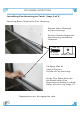
RPX ASSEMBLY INSTRUCTIONS Installing Fan Housing to Tank. Step 1 of 5. Select Base Frame and Tank Assembly for Down discharge model. 2 1 Place supplied Template to top of Tank. Align holes with template bolts. 3 4 Mark with text pen, inside edge of template. 5 Drill 6 mm hole to corners of template. Total four. 6 Remove template, place 20 mm hole saw to 6mm hole and drill through. Total four. 5 Use Jig saw and cut along marked line.
RPX ASSEMBLY INSTRUCTIONS Installing Fan Housing to Tank. Step 2 of 5. Installing Base Channels. Tank to accept square end of Fan Housing. Place Base Channels on Base Frame Assembly. R/H Base Channel Part No 623160. L/H Base Channel Part No 627168. Base Frame Assembly. Note: Position of Base Channel to Base Frame Assembly Insert holes for motor platform nearest to drain hole. Drain Hole. Align Base Channel holes with Base Frame holes.
RPX ASSEMBLY INSTRUCTIONS Installing Fan Housing to Tank. Step 3 of 5. All holes and fasteners will need to be sealed to ensure there are no water leaks outside the cooler. "Virginia" Sealing Putty has been supplied for this task. Place Sealing Putty to Base Frame Assembly. Clear hole before fitting channel. Base Frame Assy. Secure Base Channel to Base Frame. BOLT M8x30 P/N0 628257 NUT M8 8x19mm P/No 628288 P/No WAS163 At this stage do not fully tighten bolts. Refer to notes on Page 17.
RPX ASSEMBLY INSTRUCTIONS Installing Fan Housing to Tank. Step 4 of 5. Use lifting crane to raise Fan Housing and H-Frame Assembly over Base Frame Assembly. Align and lower bottom of fan housing to Tank cut out. Align bottom hole of vertical channel to Base channel holes. Secure Vertical Channel to Base Channel H-Frame Vertical Channel. BOLT M8x20 P/N0 628240 NUT WASHER M8 8x19mm P/No 628288 P/No WAS163 Note: 2 Bolts, 4 Washers and 2 Nuts per vertical Channel. Base Channel.
RPX ASSEMBLY INSTRUCTIONS Installing Fan Housing to Tank. Step 5 of 5. Securing Base Channel to Fan Housing. Secure Base Channel to Fan Housing. Fix two Screws between Fan Housing and Base Channel. SCREW - Phlp. 6x25 mm P/No SCR 384 SPIRE NUT - P/No FAS115. Fit Spire Nut to end of Screws. Inside of Fan Housing. Note: The Spire Nut can be fitted when Fan Housing assembly is tilted. Refer to notes on Page 13. Repeat process for opposite side.
RPX ASSEMBLY INSTRUCTIONS Installing Top Channel. Install Top/Bearing Channel to Vertical Channels. Part N/o 623139 Secure Channels. Tighten all bolts. BOLT M8x20 P/N0 628240 NUT WASHER M8 8x19mm P/No 628288 P/No WAS163 Repeat process for other end. 10 Repeat process for opposite side.
RPX ASSEMBLY INSTRUCTIONS Sealing Fan Housing to Tank. Step 1 of 2. Apply a generous bead of silicone sealant along Fan Housing and Tank. Fan Housing Tank FAN HOUSING FLASHING ANGLE SILICONE TANK Illustrated assembly view. Apply silicone sealant bead to Flashing Angle. Flashing Angle P/No 100152 Place Flashing Angle to Fan Housing and Tank.
RPX ASSEMBLY INSTRUCTIONS Sealing Fan Housing to Tank. Step 2 of 2. Secure Flashing Angle to Fan Housing and Tank, with supplied screws: Total 10 places. SCREW - Phlp. 4x25 mm P/No SCR506 Note: If end of fan housing bows inwards and cannot be easily fixed, a special clamp can be utilised to aid fixing. P49 has details to enable manufacture of clamp. Apply additional silicone to top and bottom edge of Flashing Angle. Check that silicone has a good seal to Fan Housing and Tank.
RPX ASSEMBLY INSTRUCTIONS Sealing Fan Housing to Tank Bottom. Use crane to tilt cooler. Silicone sealant between Fan Housing and Tank, apply thick bead to all four sides. Fit spire nut to ends of screws. Refer to notes on Page 9. SPIRE NUT - P/No FAS 115. Use crane and raise cooler to up right position.
RPX ASSEMBLY INSTRUCTIONS Prepare Motor and Controls. Step 1 of 4. Place Motor Platform to a suitable work bench. Note: Control box mounting holes. Place Control Box and water pump assembly to motor platform. Securing Control Box panel to Motor Platform.
RPX ASSEMBLY INSTRUCTIONS Prepare Motor and Controls. Step 2 of 4. Use crane and fit electric motor to platform, align holes and secure with supplied fasteners. Secure Motor to Platform. BOLT M8x30 P/N0 628257 NUT M8 8x19mm P/No 628288 P/No WAS163 Repeat for all 4 motor mounting bolts. Ensure motor is square to Platform. Tighten all bolts.
RPX ASSEMBLY INSTRUCTIONS Prepare Motor and Controls. Step 3 of 4. Feed seven wires from the electrcal control box wiring loom through the motor terminal cover opening. Attach all wires and secure motor terminal cover. Motor terminal cover. Wiring loom to electrical control box. Gland Wire connection. For low speed connect. Wire, tag numbered 1 to U1 2 to V1 3 to W1 For high speed connect. Wire, tag numbered 4 to W2 5 to U2 6 to V2 Connect earth wire to motor casing earth point.
RPX ASSEMBLY INSTRUCTIONS Prepare Motor and Controls. Step 4 of 4. Motor Pulley Attachment The motor pulley attaches to the motor shaft via a Taper Lock Bush screwed to the Pulley. Do not fully tighten Bush locking screws now, Pulley may need to move on shaft to align V-Belts. Use crane to install Motor Platform to Base Channels. Base Channel. Secure Motor Platform to Base Channels. BOLT WASHER M8x30 P/N0 628257 8x25mm P/No 627984 At this stage do not fully tighten. Refer to notes Belt Tension, P19.
RPX ASSEMBLY INSTRUCTIONS Fan Pulley Attachment. Fit 460 mm Aluminium Pulley to the fan shaft. Apply small amount Loctite 222 (not supplied) to Grub screws. Total 3 Grub screws. GRUB SCREW 5/16 BSW 19 mm Long P/No SCR433 Tighten All screws. Allow shaft to extend approx 15mm passed pulley. Use suitable straight edge, align Fan Pulley to Motor Pulley. Align Fan Pulley and Motor Pulley. Lock Screws on Motor Pulley Taper Bush.
RPX ASSEMBLY INSTRUCTIONS Fit and Tension V-belts. Fit two A91 supplied belts. Apply tension to belts. Tighten all bolts. Repeat same for opposite side. Use a suitable belt tension measuring tool, Set for recommended belt tension. Deflection (cm) 1 Force (Kg) 1.5/1.7 If belt tension is not correct, loosen bolts and move Motor Assembly, re-tension and tighten bolts.
RPX ASSEMBLY INSTRUCTIONS Fitting the Water Pumps. Position the two pumps at the corner of the tank, nearest control box. Use pump brackets as template drill 4 mm holes. Secure pumps with supplied screws. SCREW - Phlp. 5x19 mm P/No 9610013 Ensure pumps leads are out of water. Secure pumps leads with supplied cable ties, P/No FAS 213.
RPX ASSEMBLY INSTRUCTIONS Connecting the water system. Connect water hoses to pumps. Restrictor Valve. Bleed Tap assembly, (see later notes p40). Connecting the Water Inlet and Float Secure with supplied fasteners. BOLT M6x20 P/N0 628226 Installing the Anti-Vortex panels. NUT WASHER M6 6x14mm P/No 628271 P/No WAS029 Remove plastic film from panel, and secure with supplied rivets. RIVET 5X12 mm P/No FAS 032 Note: Align Centre of Anti-Vortex panel to fan housing. 21 Repeat same for opposite side.
RPX ASSEMBLY INSTRUCTIONS Corner Pillar Installation. Remove plastic protective film. Corner Pillar. Plastic protective film. Rivet Corner Pillar to Base Frame. Note: Hole location on corner pillar. RIVET 5X12 mm P/No FAS 032 At this stage two rivets only, other rivets will be fitted, when cooler is squared, see notes Final Riveting P39. Repeat for all corners of Base Frame.
RPX ASSEMBLY INSTRUCTIONS Centre Rail Installation. Corner Pillar. Centre Rail. Align two tabs on Centre Rail to slots on Corner Pillar. RIVET 5X12 mm P/No FAS 032 One Rivet, for each end. 23 Repeat same for other end. Apply silicone to folded tag.
RPX ASSEMBLY INSTRUCTIONS Top Rail Installation. Step 1 of 2. Note: Tab at each end of rail. Remove protective plastic cover. Fit Universal Bracket to Top Rail before fitting to Corner Pillar. Rivet Universal Bracket to Top Rail. RIVET 5X12 mm P/No FAS 032 Two Rivets. Universal Bracket P/No 626567.
RPX ASSEMBLY INSTRUCTIONS Top Rail Installation. Step 2 of 2. Fit Top Rail to Corner Pillar. Align one tab on Top Rail, to slots on Corner Pillar. Ensure Top Rail is hard against Corner Pillar. Use suitable pliers twist Top Rail end tab inside Corner Pillar. This to ensure that assembly will not dislodge. Top Rail. Centre Rail. 25 Repeat same for all Top Rails.
RPX ASSEMBLY INSTRUCTIONS Bottom Rail Installation. Bottom Rail. Base Frame. Place Bottom Rail to inside edge of Base Frame and Rivet, to eight points. RIVET 5X12 mm P/No FAS 032 Repeat same for other three sides. Completed Assembly Top, Centre and Bottom Rails.
RPX ASSEMBLY INSTRUCTIONS Centre Pillar Installation Select Centre Pillar and slide through Centre Rail slot. Centre Rail. Centre Pillar. Bottom Rail. Ensure Centre Pillar end tab slots to Bottom Rail. Slightly raise centre of Top Rail, until Centre Pillar end tab passes through slot. Do not fold tab.
RPX ASSEMBLY INSTRUCTIONS Water Spreader Installation. Water Spreaders. Align holes on Water Spreader to Top Rail and Rivet. RIVET 3.2X8 mm P/No FAS 300 Repeat same for other three sides. Water Distributor Cap.
RPX ASSEMBLY INSTRUCTIONS Distributor Cap Installation. Fit Distribution Cap to top of Water Spreader. No securing is required, ensure cap is tightly pressed in position. Repeat same for all Water Spreaders. Note: Position of Distribution Cap to Water Spreader. Complete assembly of Water Spreaders and Distributor Cap. Repeat same for other three sides.
RPX ASSEMBLY INSTRUCTIONS Water Distribution Connection. Step 1 of 2. Cooler is fitted with two Water Pumps. L/H side Water Pump supply hose. R/H side Water Pump supply hose. Typical hose connection to Water Spreders Inlet. 8 places.
RPX ASSEMBLY INSTRUCTIONS Water Distribution Connection. Step 2 of 2. CONNECT TO PUMP 1 1 Water Pump (2) Supply hose. CONNECT TO PUMP 2 2 Fit saddle to secure four way Distributor. Typical Hose Connection to Water Spreaders. D&T Models. Hoses may need to be trimmed to suitable length. Incorrect length Water supply hose. 31 Hoses when fitted should not touch pads. Repeat same for All water supply Hoses.
RPX ASSEMBLY INSTRUCTIONS Installing Cab Top Blanking Cover. 1 2 Remove film from cut out. Select T Model Cabinet Top, place to suitable work frame. 4 3 Fit Cab Top Blanking Cover. Apply small bead of Silicone along cut out inside line of rivet holes. 6 5 Rivet Blanking Cover to Cab Top. Check alignment, for rivet clearance holes.
RPX ASSEMBLY INSTRUCTIONS Cabinet Top Installation. Step 1 of 2. Place Cabinet Top onto Corner Pillars. Note: Position of Cabinet Top joined section.
RPX ASSEMBLY INSTRUCTIONS Cabinet Top Installation. Step 2 of 2. Cabinet Top. Remove plastic protective cover , from corners of Cabinet Top. Rivet Cabinet Top Corners. RIVET 5X12 mm P/No FAS 032 At this stage two rivets only. Other rivets will be added when cooler is squared. See notes Final Riveting P39. Repeat same for all corners.
RPX ASSEMBLY INSTRUCTIONS Squaring the Cooler for Final Assembly. Use Supplied Braces to diagonally square cooler. Fit all 4 Braces If necessary drill 5 mm hole to clear aligning holes. 35 Distance between hole centres 1868mm.
RPX ASSEMBLY INSTRUCTIONS Cabinet Top Final Assembly. Step 1 of 3. Top Channel. Drill two 12.5mm holes through Top Channel and Cab Top. Drill one 6mm hole to centre Top Channel. Note: Use 12.5 and 6 mm holes on Top Channel as guide. Repeat same for other side. Place plastic Washers between Cabinet Top and Top Channel. Place one Washers at each end. PLASTIC FLAT WASHER 6.5X50X5MM P/No WAS121 Two washers to centre. Dome effect to Cab Top, for water run off.
RPX ASSEMBLY INSTRUCTIONS Cabinet Top Final Assembly. Step 2 of 3. Fit screw and washer, to centre hole of Top Channel, through to plastic washers and Top Channel. SCREW - Phlp. Washer SPIRE NUT 6x50 mm P/No SCR 507 6x14mm P/No WAS029 P/No FAS 115. Note: Position of Spire Nut. Screw (air) driver. Pliers. Use suitable pliers to hold Spire nut. Secure Cabinet Top. Repeat same for opposite side.
RPX ASSEMBLY INSTRUCTIONS Cabinet Top Final Assembly. Step 3 of 3. Attach Lifting Eyenut to Cooler EYE NUT WASHER P/No 608358 14x25mm P/No 802138. Fit washer under Eyenut. BOLT M12x30 P/N0 608174 WASHER 13x44mm P/No 608372 Fit bolt and washer, thru 12.5 mm holes in Top Channel, through two plastic Washers, Cabinet Top and Eyenut. Secure and tighten. Repeat same for other three lifting Eyenuts. When completed, remove all squaring braces.
RPX ASSEMBLY INSTRUCTIONS Final Riveting Rivet to four Cabinet Top corners. Rivet the four Corner pillars at the Base Frame. If necessary drill 5mm to clear holes. RIVET 5X12 mm P/No FAS 032 Cab Top Nylon Washer. Universal Bracket. Fasten thru Cabinet Top Rail and Bracket. 39 RIVET 5X18 mm NYLON WASHER P/No FAS 118 P/No 629872 Fit Nylon Washer between Cab Top and Universal Bracket. Repeat same for other three sides.
RPX ASSEMBLY INSTRUCTIONS Installation of Bleed Valve. Place Bleed Sticker on Corner Pillar over hole Pass bleed tap valve through hole opening and fit rubber Grommet over valve body. GROMMET BLEED VALVE P/No 999236 Note: Apply some White Petroleum Jelly, or other similar lubricant to Grommet for ease of installation. Cable tie bleed hoses together. GROMMET BLANK P/No 626932 40 Fit Blank Grommet to other three holes.
RPX ASSEMBLY INSTRUCTIONS Clean and Test Cooler. Step 1: Check that all fasteners are tightly secured, and all riveting is completed. Step 2: Remove all plastic covering from panels. Step 3: Vacuum clean inside tank. Step 4: Use cloth and suitable cleaning solution, wipe down inside and outside of cooler. Step 5: Set overloads for High and Low speeds, as per electric motor ratings. Step 6: Test cooler for normal running conditions.
RPX ASSEMBLY INSTRUCTIONS Washers part numbers. Washer 5.6x11x 0.8mm. SS P/No WAS031 Washer 6x14x1.2mm. SS P/No WAS029 Washer 8x19x1.2mm. SS P/No WAS163 Washer 9x25x1.5mm. SS P/No WAS035 Washer 14x25x1.5mm. SS P/No 802138 Washer13x44x2.5mm G/Bond P/No 608372 Washer 6.5x50 x5mm Poly. P/No WAS 121 Washer 13x50x5mm Poly. P/No 608303 Washer 9x25x2.
RPX ASSEMBLY INSTRUCTIONS Bolts and nuts part numbers. Bolt M6x20. SS. P/No 628226 Bolt M12x30. SS. P/No 608174 Nut M6 Nyloc SS. P/No 628271 43 Bolt M8x20. SS. Bolt M8x30. SS. P/No 628240 P/No 628257 Grub screw 5/16 BSW 19mm long. P/No SCR433 Nut M8 Nyloc SS. P/No 628288 Eyenut M12 P/No 608358 Note: Stainless steel bolts and nuts are used in the assembly of coolers. A thread lubricating compound anti seize should be used at assembly. Anti Seize not supplied.
RPX ASSEMBLY INSTRUCTIONS Screws and rivets part numbers. Screw 19x5mm Phlp. SS. Screw 50x6mm Phlp. SS. P/No 9610013 P/No SCR507 P/No FAS118 P/No SCR506 44 P/No FAS300 P/No SCR 384 Rivet 5x18mm Al. Wafer Screw 25x4mm Phlp. Rivet 3.2x8mm Al. Screw 25x6mm Phlp. SS. Rivet 5x12mm Al. P/No FAS032 Rivet 5x25mm Al.
RPX ASSEMBLY INSTRUCTIONS Panels part numbers.
RPX ASSEMBLY INSTRUCTIONS Panels part numbers, cont. Motor Platform P/No 623184 Water spreader P/No 506609 Flashing Angle.
RPX ASSEMBLY INSTRUCTIONS Misc. part numbers. Label Bleed Control. Label O/Load Instructions. P/No 998053. P/No 025101 Grommet Blank. Grommet Bleed Valve. Cable Tie 140mm. P/No 626932 P/No 999236 P/No FAS213. 125 x2A Mtr Pulley. Bush Taper Lock.. 460mm Pulley. P/No 822044. P/No 111500 P/No 626987. 47 Label Serial Number.
RPX ASSEMBLY INSTRUCTIONS Misc. part numbers, cont. Overflow Assy. P/No 609737. 2 Speed switch Assy. P/No 626680 P/No 200103 A Section V Belts. Silicone Sealant. P/No Vba91. P/No MIS508. Down Discharge Template cutout. Distance between pin centres 1868mm. Diagonally square braces. 48 Mounting block.
RPX ASSEMBLY INSTRUCTIONS Special jig to assist when securing Flashing Angle to Fan Housing. Note: Cooler must be on pallet Place tool to centre of cooler, lever upwards to push inside of fan housing to flashing angle.
RPX 900 'D' KIT. RESERVOIR, BASE FRAME AND ACCESSORIES. 50 FAN HOUSING AND 'H' FRAME ASSEMBLY.
RPX 900 'D' KIT. CABINET TOP 'D' ASSEMBLY. HARDWARE KIT 9655147. 51 PADS ASSEMBLY.
45 TEL (02) 60411611 FAX (02) 60412208 77 North Street, Albury N.S.W. www.braemar.com.
627168 33 627236 111500 822044 608358 VBA91 627892 630342 100156 56 57 59 60 61 62 63 608907 53 626987 999293 52 55 523002 51 54 506609 626482 50 627229 48 49 620992 47 2 4 1 2 Vee Belt A91 Centre Pillar Grey Blanking Plate - RPX "T" Cab Top Flashing Strip Unpainted 4 Pulley Fan 450 (18") x 2A x 31.
INDUSTRIAL AIR CONDITIONERS Advanced natural cooling 1 B R OW N A1 A2 L3 1200-1800 B LUE R PX B LUE WHIT E L2 B LUE W HIT E B LAC K GR E Y RED 3 L1 B LAC K (Neutral) 2 F AN HI F AN LO AC T IV E N IS OLAT ING S W IT C H T O E AR T H P OINT 1 GR E Y C ool 3AG 250V Lo/Hi E WHIT E 600-1000 TO T E R MINAL P OINT 6 2 5A F US E 1 C 2 RED C 2 P UMP C MAINS IN E B LUE R PX RED F an 1 L3 N IS OLAT ING S W IT C H W ALL S W IT C H 1 L2 WHIT E L1 RED 3 P HAS E W IR I