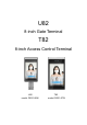
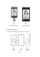
U82 8-inch Gate Terminal T82 8-inch Access Control Terminal U82 model: DR21-8UW T82 model: DE21-8TW
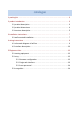
catalogue 1 packing list ························································································3 2 product introduction·············································································3 2.1 product description ····································································3 2.2 product dimensions ···································································4 2.
statement Without the written permission of the company, no unit or individual shall extract or copy part or all of the contents of this manual without authorization, and shall not disseminate it in any form. Due to product version upgrade or other reasons, the contents of this manual will be updated from time to time. This manual is only used as a guide, and all statements, information and suggestions in this manual do not constitute any express or implied warranty.
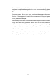
After installation, please check the correctness to avoid human injury and equipment component damage due to wrong connection during power on. Abnormal power failure may cause equipment damage or abnormal function. If the equipment is used in the environment of frequent power failure, please provide ups.
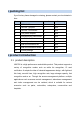
1 packing list If you find any items damaged or missing, please contact your local dealer in time. No item number unit 1 DR21-8UW 1 pcs 2 Tail line - grid port 1 pcs 3 Tail line - full function 1 pcs 4 The power adapter 1 pcs 5 Accompanying instructions 1 pcs 6 certificate 1 pcs 7 warranty card 1 pcs 8 Wall mount bracket set 1 pcs 9 Wall mount bracket sticker 1 pcs 10 Screw package 1 pcs 2 product introduction 2.
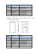
U82 T82 model: DR21-8UW model: DE21-8TW 2.2 product dimensions U82 Equipment dimension drawing, as shown in Figure 2-1.
T82 Equipment dimension drawing, as shown in Figure 2-2. chart 2-2 2.3 structure description The appearance of U82 equipment structure is shown in Figure 2-3. Please refer to the real object for details.
Serial number name explain 1 Led fill light Fill RGB camera 2 Infrared fill light Fill in light for infrared camera 3 Infrared camera Take infrared images 4 RGB camera Take visible images 5 speaker Play voice prompt 6 Tail line output hole Panel tail line hole The appearance of T82 equipment structure is shown in Figure 2-4. Please refer to the real object for details.
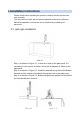
3 installation instructions Please check before installing the product to ensure that the product can work normally. This document provides wall mounted installation methods for reference, and other installation instructions can be obtained by contacting our personnel; 3.
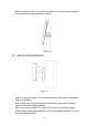
Step 4: as shown in Fig. 3-4, loosen the screw on the upright support, adjust it to an appropriate angle and tighten it again; chart 3-4 3.
Step 4: as shown in Figure 3-5, fasten the access control terminal sheet metal to the wall hanging support through position ③; Step 5: as shown in Figure 3-5, use screws ④ to fix the access control terminal and the wall hanging bracket; Step 6: after installation, as shown in Figure 3-6; chart 3-6 4 wiring instructions 4.
U82 interface description Serial number Interface name P1 RJ45 network port P2 Pin color Pin description Wired network port communication / RJ45 network port 12V power supply 12V power input / DC_12V P3 USB2.0 USB2.
4.2 T82 schematic diagram of tail line chart 4-2 T82 interface description Serial number Interface name P1 RJ45 network port P2 Pin color Pin description Wired network port communication / RJ45 network port 12V power supply 12V power input / DC_12V P3 USB2.0 USB2.
communication P7 P8 WG_OUT ALM_IN、 SEN_IN 5 Equipment Wigan signal output Alarm signal input, door magnetic signal input RED 5V WHITE/PURPL E RS485+ BROWN RS485- BLACK GND YELLOW/GRAY WG_OUT_D 0 WHITE/YELLO W WG_OUT_D 1 BLACK GND PINK ALM_IN1 YELLOW/BLAC K ALM_IN2 WHITE/GREEN SEN_IN1 Use 5.1 starting equipment After correct installation, connect the power adapter to the mains and the other end to the equipment power interface to start the equipment.
5.2.2 login web interface 1. DHCP login (factory default DHCP); Enter the IP address in the upper left corner of the device display in the browser to enter the web login interface, as shown in Figure 5-1 and figure 5-1 chart 5-1 IP display of main interface chart 5-2 IP access of input device 2.Static IP login: Step 1: click the < setting > button on the device display screen interface; Enter the initial password < admin > to enter the network configuration interface.
Default user name: admin; Default password: admin. 5.2.3 new personnel 1. Select [personnel management - personnel information] interface and select the personnel library to add personnel; 2. In the personnel list operation bar, click < add >; 3. In the pop-up new personnel interface, refer to the following table to configure personnel information; 4. Click < save > to finish adding personnel. 5.
§ 15.21 Information to user. Any Changes or modifications not expressly approved by the party responsible for compliance could void the user's authority to operate the equipment. § 15.105 Information to the user. Note: This equipment has been tested and found to comply with the limits for a Class B digital device, pursuant to part 15 of the FCC Rules. These limits are designed to provide reasonable protection against harmful interference in a residential installation.