
Operation Manual


Looking at or near the Sun will cause instant and irreversible damage to your eye!
8
Assembling (Exos1)
Telescope Assembly
As you unpack your telescope, carefully note the following parts. The
assembly is shipped in separate boxes.
• Equatorial mount with polar alignment finder
• Heavy duty, adjustable steel tube tripod with leg braces, three tripod leg
lock knobs, and a captive mount locking knob
• Complete optical tube assembly including primary mirror with dust cover
and a rack-and-pinion focuser and eyepiece holders for both 1.25“ and 2“
eyepiece holders, tube cradle assembly with two rings and two lock knobs
• Eyepiece
• Counterweight and counterweight shaft. Some models include an
additional counterweight.
• 8 x 50mm or 6 x 30mm viewfinder
How to Assemble Your Telescope
The giftboxes contain the optical tube assembly and the tripod with the
equatorial mount. The accessories are located within compartments custom-
cut into the styrofoam block inserts.
instructions on telescope assembly. The packaging contains the main tube
and tripod components, the tripod with mounting and accessories.
1. Remove the components from the packaging and familiarise yourself
with them. Please refer to illustrations 1a to 1d for details of telescope
assembly. When removing the tripod from its packaging keep it parallel
to the floor as the inner legs may otherwise slide out as they are not yet
screwed tight.
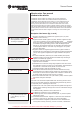
2. Assembly - tripod: The tripod legs are preassembled and already con-
nected to the tripod head and accessory tray. Remove the tripod from
the packaging and place it in front of you, with the tripod legs on the
floor. Grab two legs and pull them apart until fully spread out. The tripod
weight rests only on one leg. Now level the tripod and adjust third leg if
necessary. Pull out the bottom part of the leg to the desired length (Fig.
2b) and lock with the locking knob (3 pieces total) to a firm feel. Be care-
ful not to over tighten the screws! These screws lock the inner leg seg-
ments to the desired tripod height.
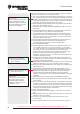
3. Assembly - mounting accessory tray: The accessory tray (Fig.: 2a) Is
placed on the tripod spider with the flat side facing down, then locked in
place turning the tray approximately 60° clockwise. The three gudgeons
of the tray should be centered on the spider vanes and lock in place.
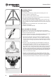
Fig. 2a: The tripod
Fig. 2b: tripod leg locks
Fig. 2c: Tripod head
Fig. 2d: central mount locking
screw
as s e m b l I n G ex o s 1