
Operation Manual


Assembling (Exos2)
Telescope Assembly
As you unpack your telescope, carefully note the following parts. The assem-
bly is shipped in separate boxes.
• Equatorial mount with polar alignment finder
• Heavy duty, adjustable steel tube tripod with leg braces, three tripod leg
lock knobs, and a captive mount locking knob
• Complete optical tube assembly including primary mirror with dust cover
and a rack-and-pinion focuser and eyepiece holders for both 1.25“ and 2“
eyepiece holders, tube cradle assembly with two rings and two lock knobs
• Eyepiece
• Counterweight and counterweight shaft. Some models include an additional
counterweight.
• 8 x 50mm or 6 x 30mm viewfinder
How to Assemble Your Telescope
The giftboxes contain the optical tube assembly and the tripod with the equa-
torial mount. The accessories are located within compartments custom-cut
into the styrofoam block inserts.
instructions on telescope assembly. The packaging contains the main tube
and tripod components, the tripod with mounting and accessories.
1. Remove the components from the packaging and familiarise yourself
with them. Please refer to illustrations 1a to 1d for details of telescope
assembly. When removing the tripod from its packaging keep it parallel
to the floor as the inner legs may otherwise slide out as they are not yet
screwed tight.
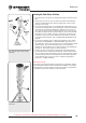
2. Locking the tripod legs. Spread the legs until the spider vanes of the
accessory plate are tautened (illustration. 3).
3. Fastening the spacing plate in place. To fasten the central screw (illustra-
tion 4, A) on the tripod first screw the tensioning screw (illustration 4, B)
on. This can be screwed right down as it serves to clamp the spacing
plate against the tripod legs. You can now insert the plate (illustration 4,
C) from above on the central screw. Make sure the plate bars (illustra-
tion 4, D) show downwards. Caution. It‘s important the following step is
applied to prevent thread damage. To prevent the threaded rod (illustra-
tion 4, E) being screwed into the mount too far use the gapping washer
(illustration 4, F) supplied. Insert it from above on the threaded rod so
that the wider chamfered side shows downwards. The spacing ring must
be on the threaded rod „step“. Now push the threaded rod from below
through the tripod base and slide the c-clip (illustration 4a, A) on the
recess (illustration 4a, B) in the threaded rod
4b. Fastening the mount on the tripod top. Place the mounting on the tri-
pod top. Make sure the projection on the tripod is between the azimuth
adjustment screws (illustration 5). To do so first loosen the azimuth
screws sufficiently to allow space for the projection. Place the mounting
on the tripod top in such a way that the projecting cylinder on the base
fits into the hole in the tripod base centre and fasten it in place using the
central screw. Tighten the screw hand tight.
5. Fastening the counterweight on the counterweight rod: insert the base of
the counterweight rod (20, illustration 1d) on the threaded end of the rod
and screw it on the counterweight rod (22, illustration 1). Then screw both
in the thread on the base of the declination axis and counter screw rod to
base. If you look through the large drill hole in the counterweight you will
see the bolt blocking the hole. Move the counterweight slightly to make
Looking at or near the Sun will cause instant and irreversible damage to your eye!
11
as s e m b l I n G ex o s 2
Fig. 3: The tripod
Fig. 5: installing the mounting on
the tripod.
Fig. 4: Fastening the spacing plate
and distance washer in place.
E
F
E
C
B
A
D
Fig. 4a: Threaded rod fastening
using the C-clip
A
B
Gudgeon
Azimuth
fine adjust-
ment