LAP24EULBA LAP24EULFR NOTEBOOK CART ASSEMBLY WITH TIMER Assembly Instructions for: INTERIOR E-UNIT REPOSITIONING / REPLACEMENT AND TIMER REPLACEMENT LAP24EULBA CAUTION: RISK OF ELECTRICAL SHOCK. DO NOT PLUG INTO ANOTHER RELOCATABLE POWER TAP. Parts List Qty. 1 Part No. LAP24EULBA LAP24EULFR Description Cart Assembly, e-units at back Cart Assembly, e-units at front Tools Required NO TV/MONITOR TO BE USED ON TOP OF CART MAXIMUM WEIGHT OF ACCESSORIES ON TOP OF CART: 25 LBS.
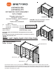
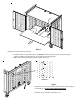
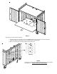
timer assembly E-Unit power cord bottom shelf Front View bracket assembly DETAIL 'B' clip bracket assembly DETAIL 'A'
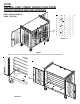
front-left front-right Step 2 Remove front-left E-Unit by griping the top and tilt it side ways until it clears the underside of the cart interior shelf channel and set it aside. Remove front-right E-Unit by griping the top and tilt it side ways until it clears the underside of the cart interior shelf channel and set it aside. DETAIL 'C' Step 3 Remove 14 screws (2 per shelf) from rear panel that secure the 7 interior shelves (see DETAIL 'C').
mounting tab DETAIL 'D' Step 4 Remove each interior shelf by carefully pushing upward (to release shelf from mounting tabs) shown in Detail 'D', then carefully sliding out. Set each shelf aside.
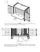
cutout window clip-rear Step 5 Reinstall the E-Units (set aside from being removed from the front) as follows: 1. Rotate the E-Unit 180 degrees (from original position). 2. Position to the rear of cart. 3. Tilt in and set bottom in back, in front of rear panel cutout window. 4. Grip the top and tilt to the upright position, underneath top panel bracket. When repositioned correctly, the E-Unit power switch should be visible from rear panel cutout window.
tab notch Step 6 Reinstall the 7 interior shelves as follows: 1. Carefully slide in the shelf with notch, at the bottom position (the notch will rest on the bracket tab). (Make sure that the shelf flanges are ALL seated into the mounting tabs.) 2. Slide in all remaining shelves into position as the bottom shelf. DETAIL 'E' Step 7 Reinstall 14 screws to rear panel that will secure the 7 interior shelves (see DETAIL 'E). DO NOT OVER TIGHTEN SCREWS. Installation is now complete and ready for use.
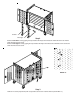
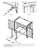
NOTE: UNPLUG CART (TIMER) POWER CORD FROM POWER SOURCE BEFORE STARTING E-UNIT REPOSITIONING: 'REAR TO FRONT' DETAIL 'A' Step 1 Remove 14 screws (2 per shelf) from rear panel that secure the 7 interior shelves (see DETAIL 'A').
Step 2 With both doors open, remove each interior shelf by carefully pushing upward (to release shelf from mounting tabs) shown in Detail 'B', then carefully sliding out. Set each shelf aside. timer assembly E-Unit power cord Front View Carefully unplug the power cords of the E-Units from the timer assembly (see Front View) and unclip the power cords from the clips at the rear of cart. Loosen the screw holding the E-Unit bracket assembly and remove all 4 bracket assemblies (see DETAILS 'D' and 'E').
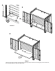
DETAIL 'D' DETAIL 'D' DETAIL 'E' rear-left rear-right Step 3 Remove rear-left E-Unit by griping the top and tilt it side ways until it clears the underside of the cart interior shelf bracket and set it aside. Remove rear-right E-Unit by griping the top and tilt it side ways until it clears the underside of the cart interior shelf bracket and set it aside.
notch tab Step 4 Reinstall the 7 interior shelves as follows: 1. Carefully slide in the shelf with notch at the bottom position (the notch will rest on the bracket tab). (Make sure that the shelf flanges are ALL seated into the mounting tabs.) 2. Slide in all remaining shelves into position as the bottom shelf. DETAIL 'F Step 5 Reinstall 14 screws to rear panel that will secure the 7 interior shelves (see DETAIL 'F'). DO NOT OVER TIGHTEN SCREWS.
offset clip Step 6 Reinstall the E-Units (set aside from being removed from the rear) as follows: 1. Rotate the E-Unit 180 degrees (from original position). 2. Position to the front of cart. 3. Tilt in and set against offset of bottom panel (of cart). 4. Grip the top and tilt to the upright position. When repositioned correctly, the E-Unit power switch should face the front.
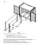
NOTE: UNPLUG CART (TIMER) POWER CORD FROM POWER SOURCE BEFORE STARTING E-UNIT REPLACEMENT: 'REAR LOCATION' DETAIL 'A' Step 1 Remove 14 screws (2 per shelf) from rear panel that secure the 7 interior shelves (see DETAIL 'A').
Step 2 With both doors open, remove each interior shelf by carefully pushing upward (to release shelf from mounting tabs) shown in Detail 'B', then carefully sliding out. Set each shelf aside. timer assembly E-Unit power cord Front View Carefully unplug the power cord(s) of the E-Unit(s) from the timer assembly (see Front View) and unclip the power cord(s) from the clip(s) at the rear of cart. Loosen the screw holding the E-Unit bracket assembly and remove each bracket assembly (see DETAILS 'C' and 'D').
DETAIL 'C' DETAIL 'D' rear-left rear-right Step 3 Remove E-Unit(s) by griping the top and tilt it side ways until it clears the underside of the cart interior shelf bracket and set it aside.
cutout window clip Step 4 Carefully install replacement E-Unit(s) into position by placing bottom in first and tilting in sideways to the top. When repositioned correctly, the E-Unit(s) power switch should be visible from rear panel cutout window. Reinstall the E-Unit bracket assemblies (make sure that the top flange of the E-unit is aligned with the slot in the bracket assembly) and tighten screws securely. Plug in the E-Unit(s) power cord(s) into the bottom outlet(s) of the timer assembly.
tab notch Step 5 Reinstall the 7 interior shelves as follows: 1. Carefully slide in the shelf with notch, at the bottom position (the notch will rest on the bracket tab). (Make sure that the shelf flanges are ALL seated into the mounting tabs.) 2. Slide in all remaining shelves into position as the bottom shelf. DETAIL 'E' Step 6 Reinstall 14 screws to rear panel that will secure the 7 interior shelves (see DETAIL 'E). DO NOT OVER TIGHTEN SCREWS. Installation is now complete and ready for use.
NOTE: UNPLUG CART (TIMER) POWER CORD FROM POWER SOURCE BEFORE STARTING E-UNIT REPLACEMENT: 'FRONT LOCATION' SEE DETAIL 'B' bottom shelf SEE DETAIL 'A' Step 1 Open both front doors of cart to access E-Unit(s). From underneath the bottom shelf, carefully unplug the power cord of the E-Unit(s) from the timer assembly (see Front View) and unclip the power cord(s) from the bottom of cart.
bracket assembly clip DETAIL 'B' bracket assembly DETAIL 'A' front-left front-right Step 2 Remove E-Unit(s) by griping the top and tilt it side ways until it clears the underside of the cart interior shelf channel and set it aside.
front-left front-right bottom shelf Step 3 Carefully install replacement E-Unit(s) into position by placing bottom in first and tilting it in sideways to the top. When repositioned correctly, the E-Unit(s) power switch should face the front. Reinstall the E-Unit bracket assemblies (make sure that the top flange of the E-unit is aligned with the slot in the bracket assembly) and tighten screws securely.
NOTE: UNPLUG CART (TIMER) POWER CORD FROM POWER SOURCE BEFORE STARTING TIMER REPLACEMENT: 'E-UNIT AT REAR LOCATION' DETAIL 'A' Step 1 Remove 6 screws (2 per shelf) from rear panel that secure the 3 bottom interior shelves (see DETAIL 'A').
Step 2 With both doors open, remove the 3 bottom interior shelves by carefully pushing upward (to release shelf from mounting tabs) shown in Detail 'B', then carefully sliding out. Set each shelf aside. timer assembly E-Unit power cord Front View Carefully unplug the power cords of the E-Units from the timer assembly (see Front View).
E-Unit bracket assembly bottom flangetimer/bracket Step 3 Remove 2 screws from bottom flange (securing bracket to bottom of cart) and remove timer/bracket assembly. The E-Unit bracket assembly shown above, will need to be removed (with a philips screwdriver) to allow the EUnit to swing back. This will allow the timer cord plug to pass between the E-Unit and rear panel. Step 4 Remove 2 screws that secure timer to bracket.
Timer vents & bracket must be attached as shown. Step 5 Install bracket to replacement timer with 2 nuts. Adjust timer dial to current time. If necessary, adjust timer charging times to match the original timer. bracket assembly bottom flangetimer/bracket Step 6 Install replacement timer/bracket assembly onto bottom, rear of cart with 2 screws. Feed the power cord from the timer out the grommeted hole (with cord wrap bracket located above cutout).
notch tab Step 7 Reinstall the 3 interior shelves as follows: 1. Carefully slide in the shelf with notch at the bottom position (the notch will rest on the bracket tab). (Make sure that the shelf flanges are ALL seated into the mounting tabs.) 2. Slide in remaining 2 shelves into position as the bottom shelf. DETAIL 'C' Step 8 Reinstall 6 screws to rear panel that will secure the 3 interior shelves (see DETAIL 'C'). DO NOT OVER TIGHTEN SCREWS. Installation is now complete and ready for use.
NOTE: UNPLUG CART (TIMER) POWER CORD FROM POWER SOURCE BEFORE STARTING TIMER REPLACEMENT: 'E-UNIT AT FRONT LOCATION' SEE DETAIL 'B' bottom shelf SEE DETAIL 'A' Step 1 Open both front doors of cart to access E-Units. From underneath the bottom shelf, carefully unplug the power cords of the E-Units from the timer assembly (see Front View) and unclip the power cords from the 4 clips located at the bottom panel of the cart.
bracket assembly clip bracket assembly DETAIL 'B' DETAIL 'A' front-left front-right Step 2 Remove front-left E-Unit by griping the top and tilt it side ways until it clears the underside of the cart interior shelf channel and set it aside. Remove front-right E-Unit by griping the top and tilt it side ways until it clears the underside of the cart interior shelf channel and set it aside.
DETAIL 'A' Step 3 Remove 6 screws (2 per shelf) from rear panel that secure the 3 bottom interior shelves (see DETAIL 'A').
Step 4 With both doors open, remove the 3 bottom interior shelves by carefully pushing upward (to release shelf from mounting tabs) shown in Detail 'B', then carefully sliding out. Set each shelf aside. bottom flangetimer/bracket Step 5 Remove 2 screws from bottom flange (securing bracket to bottom of cart) and remove timer/bracket assembly.
Step 6 Remove 2 screws that secure timer to bracket. Timer vents & bracket must be attached as shown. Step 7 Install bracket to replacement timer with 2 nuts. Adjust timer dial to current time. If necessary, adjust timer charging times to match the original timer.
bottom flangetimer/bracket Step 8 Install replacement timer/bracket assembly onto bottom, rear of cart with 2 screws. Feed the power cord from the timer out the grommeted hole (with cord wrap bracket located above cutout). Make sure timer face is aligned with rear panel cutouts. notch tab Step 9 Reinstall the 3 interior shelves as follows: 1. Carefully slide in the shelf with notch at the bottom position (the notch will rest on the bracket tab).
DETAIL 'C' Step 10 Reinstall 6 screws to rear panel that will secure the 3 interior shelves (see DETAIL 'C'). DO NOT OVER TIGHTEN SCREWS. bottom shelf front-left front-right Step 11 Carefully reinstall E-Units into position by placing bottom in first and tilting it in sideways to the top (underneath the channel bracket of the cart top panel). When repositioned correctly, the E-Units power switch should face the front.
LABEL INSTALLATION: AUX. 1 AUX. 2 AUX. 3 AUX. 4 AUX. 5 AUX. 6 1 2 3 4 5 6 7 8 9 10 11 12 13 14 15 16 17 18 19 20 21 22 23 24 25 26 27 28 29 30 peel off and attach corresponding labels to shelves and E-Units.
PAD LOCK - DOOR: Open Lock The First Time 1) Set the combination to 0-0-0-0 2) Depress shackle and pull open. To Set You Own Combination **REMEMBER: Combination can only be set when lock is open. 1) Insert “reset” tool (included in package) in hole on side of lock. 2) Push key in and turn key 90 degrees in either direction. (Key automatically stays in this position). Failure to exert force while pushing key in will result in a failed attempt to set or reset combination.