Models 2130 and 2140 Overview ............................................................... 2 Tools Needed ........................................................ 2 Hardware............................................................... 2 Assembly.......................................................... 3-10 Installation...........................................................11 Document 101292 RevA 1 Operation ................................................................ 11 Maintenance .......
OVERVIEW COMPONENT IDENTIFICATION NOTE: Save all packaging in case re-shipment is required. Perform the following sequence in order when setting up the table: Unpacking Assembly Leveling the Table Installing the Paper Roll NOTE: Inspect all boxes and contents for damage. Report any damage to the carrier immediately. MODELS 2130 & 2140 For the above models you will receive two separate cartons: a frame carton, and an upholstery carton. Inspect both carefully for shipping incurred damage.
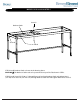
MODELS 2130 and 2140 STEP 1 Notch Screw C Screw C STEP A: Start with table frame inverted: note the position of the Notch in the drawing above is facing upwards. STEP B: Positon legs (see drawing above). Insert Screws C (1/4”-20 x 1 1/4”) and snug up by hand only at this time.
MODEL 2130 and 2140 STEP 2 Screw B Screw B Screw B Screw B Shelf Support STEP A : With table in the upright position install Shelf Support using 4 Screws B (1/4”-20 x 2”). Do not tighten at this time.
MODELS 2130 and 2140 STEP 3 Caps Tab Upper Leg Screws Head End Shelf Support STEP A: Remove 2 Upper Leg Screws at Head End of the Table, one on each of the two legs. (See illustration above.) STEP B: Insert Caps into two leg tops and seat with a rubber mallet. STEP C: Install Upper Leg Screws. STEP D: Tighten all screws at this time.
MODELS 2130 and 2140 STEP 4 Screw G Backrest Catch Screw B Nut H STEP A: Install Backrest Catch as shown in the drawing above. CAUTION ! The Backrest Catch needs to be positioned on top of the Tab shown in STEP 3. STEP B: Install Screw B (1/4”-20 x 2”) through frame rail and into Backrest Catch and tighten Nut H (1/4”-20). Insert Screw G (1/4”-20 x 1/2”) through Backrest Catch and Tab. Tighten Nut H onto Screw G.
MODELS 2130 and 2140 STEP 5 Detail of Hinge Assembly Screw G Head End Nut H STEP A: Align holes in Hinge with holes in frame. Hinge must be oriented as shown with Hinge mounting flange facing the Head End of the table. STEP B: Install 4 Screws G (1/4”-20 x 1/2”) into the Hinge and through the frame. Fasten with 4 Nuts N (1/4”-20) and tighten.
MODELS 2130 and 2140 STEP 6 J-Bolt R Screw D Bumper Screw D J-Bolt R Backrest Support Bumper Nut L Cotter Pin Screw F Washer M Screw F Clevis Pin Clevis Pin Foot End Clevis Hinge Clevis Tab STEP A: Lay upholstered backrest on Foot End of frame as shown. STEP B: Slide backrest down until it bumps up against Hinge. STEP C: Insert the four backrest-to-hinge Screws F (1/4”-20 x 1”) and tighten. STEP D: Insert Screws F (1/4”-20 x 1”) through Clevises and tighten. Note Clevis Tab orientation.
MODELS 2130 and 2140 STEP 7 Rounded Corner Back Section Foot End Backrest Bracket Screw A Screw B STEP A: Rotate Back Section until Backrest Bracket is engaged or top is horizontal on frame. STEP B: Set upholstery bottom on frame, with Rounded Corners placed at the Foot End of the table. STEP C: Install Screw A (1/4”-20 x 4”) through frame and into upholstery. STEP D: Install 2 Screws B (1/4”-20 x 2”) through frame and into upholstery. STEP E: Tighten Screws.
MODELS 2130 and 2140 STEP 8 Dowel Rod Snap Rivets Shelf Snap Rivets Lower Shelf Support STEP A: Insert the Shelf through either end of the Table. Positon the Shelf so that the locating blocks, on the bottom of the Shelf, are straddling the Lower Shelf Support. STEP B: Install Snap Rivets into unused holes in legs and frame (see illustration above). STEP C: Slide the Dowel Rod through the paper roll and hang the Dowel Rod on the J-Bolts. Ensure a secure fit before using the paper roll dispenser.
INSTALLATION Leveling the Table A Leveling Screw Pad is located at each corner under the table’s base. Adjust the four Leveling Screw Pads, by turning them up or down, to achieve a solid, level installation. Leveling Screw Pad OPERATION Back Section To Raise Back Section: Lift Back Section of upholstery to desired inclination and secure Backrest Bracket into one of the six Backrest Catch slots.
MAINTENANCE Preventative Maintenance • Inspect the mechanical functions to ensure satisfactory operation. • Check fasteners to make sure they are present and secured tightly. Painted Metal Surfaces Wipe all painted metal surfaces with a clean cloth at least once a week. ACCESSORIES Cleaning Upholstery Regular care should be maintained by daily wiping with a damp cloth or sponge and periodic cleaning with a mild soap and water solution. Let air dry before placing anything on top of upholstery.