
Owner's manual


Document 101292 RevA
Printed in USA © 2010
5
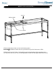
MODELS 2130 and 2140 STEP 3
STEP A: Remove 2 Upper Leg Screws at Head End of the Table, one on each of the two legs. (See illustra-
tion above.)
STEP B: Insert Caps into two leg tops and seat with a rubber mallet.
STEP C: Install Upper Leg Screws.
STEP D: Tighten all screws at this time.
-Legs to Frame (8 screws using Allen Wrench provided)
-Shelf Support to Legs (4 screws)
Tab
Caps
Head End
Upper Leg Screws
Shelf Support