
Owner's manual


Document 101292 RevA
Printed in USA © 2010
6
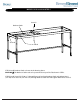
MODELS 2130 and 2140 STEP 4
Backrest Catch
Screw G
Nut H
Screw B
STEP A: Install Backrest Catch as shown in the drawing above.
CAUTION ! The Backrest Catch needs to be positioned on top of the Tab shown in STEP 3.
STEP B: Install Screw B (1/4”-20 x 2”) through frame rail and into Backrest Catch and tighten Nut H
(1/4”-20). Insert Screw G (1/4”-20 x 1/2”) through Backrest Catch and Tab. Tighten Nut H onto Screw G.