Hardware User’s Manual Megapixel Day & Night Fixed Box Network Camera Quality Service Group Fixed Box Series 0
Review History: 1. Separate User Manual into HW and SW. 2. Merge FB-100Ap/FB-100Ae/FB-130Np Series into this User Manual. 3. Merge FocusEasy™ version Product name: Network Camera (Fixed Box series) Release Date: 2013/07 Manual Revision: V4.0 Web site: www.brickcom.com Email: support@brickcom.com info@brickcom.com © 2013 Brickcom Corporation.
Table of Contents Before You Use This Product ..................................................................... 3 Regulatory Information ............................................................................ 4 Chapter 1- Package Contents .................................................................... 5 Chapter 2- Fixed Box Network Camera Overview ........................................... 6 Chapter 3-LED Behavior ...........................................................................
Before You Use This Product In many countries, there are laws prohibiting or restricting the use of surveillance devices. This Network Camera is a high-performance, web-ready camera which can be part of a flexible surveillance system. It is user’s responsibility to ensure that the operation of this camera is legal before installing this unit for its intended use. Upon opening the product’s package, verify that all the accessories listed on the “Package Contents” are included.
Regulatory Information Federal Communication Commission Interference Statement This equipment has been tested and found to comply with the limits for a Class B digital device, pursuant to Part 15 of the FCC Rules. These limits are designed to provide reasonable protection against harmful interference in a residential installation.
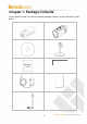
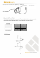
Chapter 1- Package Contents Please check to make sure that the product package contains all the accessories listed below. a. Network Camera b. CS mount Lens (Optional) c. Product CD d. Camera Stand e. Warranty Card f. Allen Key g. Power Adapter (Optional) h. Easy Installation Guide i.
Chapter 2- Fixed Box Network Camera Overview The Brickcom Fixed Box series offers a reliable and efficient solution for 24-hour video surveillance. The Fixed Box series offers highly efficient H.264 video compression, which reduces bandwidth and storage requirements without compromising image quality. M-JPEG and MPEG-4 are also supported for flexibility. With the megapixel progressive sensor and removable IR-cut Filter, this series delivers extremely clear and detailed images that CCTV cameras cannot offer.
Chapter 3-LED Indicators Function Front LED Behavior Description WPS in process WPS FocusEasy™ (V2 Series only) Steady WPS Successfully Connected Steady Lens focusing in process Remark Right (Blue) Right (red) Hardware failure Steady Normal Operation Status Unlit Power Off Left (Green) While F/W upgrading Function Rear LED Behavior Flashes Link Unlit Power Steady Unlit 7 Description Blinking while connecting to the network No connection Normal Operation Power off Remark Left (Amber)
Chapter 4- Device Appearance Description Photo Indication & Dimension Diagram Status LED Power Connector (AC24V In) Microphone/Line In Ethernet RJ45 10/100 Socket Power Connector (DC12V In) (Link/Power LED embedded) Light Sensor Detachable Antenna (WIFI series) WPS/FocusEasy™ LED WPS Button (WIFI Series) (WIFI series/FocusEasy™ series) SD/SDHC Card Slot Reset Button Extension I/O Terminal Block Audio Out Auto Iris Connector Build-in Microphone NOTE 1.
(DC Drive) --- CS Mount Zoom Controller Focus Controller Extension I/O Terminal Block The Network Camera provides an extension I/O terminal block which is used to connect the camera with external input/output devices. The pin definitions are listed as below.
Hardware Reset Reset Button The Reset Button can be used to reboot the camera or restore it to factory default settings. If the camera experiences a problem, rebooting the camera may correct the problem. If the problem remains, please restore the camera to factory default settings and reinstall the software. To Reboot - Press and hold the Reset Button for one second using a paper clip or thin object. Wait for the camera to reboot.
Chapter 5- Installation 5.1 Hardware Installation Mounting the CS-Mount Lens to the Camera --- Optional Lens 1. Connect the CS-mount lens to the IP camera by turning it clockwise. 2. If necessary, adjust the iris controller, focus controller, and zoom controller to get the best image condition. To adjust the lens: 1. Adapt the iris to current environment by adjusting iris controller (The more the iris is opened, the brighter the scene will be). 2.
3. Once the image is focused, the buzzer will make a long beep for 3 seconds for notification. --- Optional Lens 1. Connect the CS-mount lens to the camera by turning it clockwise 2. Plug the lens cable in the side camera connector. 3. If necessary, adjust focus controller, and zoom controller to get the best image condition. To adjust the lens: 1. Adjust zoom controller to decide the focal length. 2.
5.2 Minimum System Requirements CPU Pentium 4 3GHz RAM 1024 MB Web Browser Microsoft Internet Explorer 8.
5.3 Camera Connection Note: If there is no DHCP server on the network, the camera will operate with the IP address 192.168.1.245. Please make sure your computer's network interface is configured to the same subnet as the camera. Connection to Non-PoE (Power over Ethernet) Switch or Router 1) Power the camera by plugging the power adaptor to the outlet and the DC jack to the camera. 2) Connect the camera to the switch or router with the RJ-45 Ethernet cable. * Upon power-on, the rear LEDs will be lit.
Connection to PoE Switch or Router or Injector A. PoE Switch or Router: 1) Connect the camera to the PoE switch or router with the RJ-45 Ethernet cable. B. PoE injector: 1) Connect the camera to the OUT port ("DATA+Power" port, etc.) of the PoE injector with the RJ-45 Ethernet cable. 2) Connect the IN port ("DATA" port, etc.) of the PoE injector to the switch or router with the RJ-45 Ethernet cable.
Software Installation In this manual, "User" refers to whoever has access to the Network Camera, and "Administrator" refers to the person who can configure the camera and grant user to access the camera. After checking the hardware connection, run the Installation Wizard program included on the product’s CD-ROM to automatically search the intranet for the camera. There may be many cameras on the local network.
In the Install Shield Wizard dialog box, click to continue. Read the End-User License Agreement and check the option “I accept the terms of the license agreement”. Click to continue.
Select either “Complete” setup or “Custom” to install the system. COMPLETE SETUP (Recommended) Check the option “Complete” and then click . Click to change the appointed folder to install. Click to continue.
Shortcut options selection. Click to continue. The installation information will be displayed. Click to continue.
To launch EasyConfig or PC-NVR Standard, select the application and click . When launching the PC-NVR program, please refer to the PC-NVR user manual. CUSTOM SETUP This option is recommended for advanced users. It can be used to install the system to a preferred directory or to select specific program feature(s). Check the option “Custom”, and then click .
Select the features to install. Click to continue.
Click to change the appointed folder to install. Click to continue. Select programs to create shortcuts. Click to continue.
The installation information will be displayed. Click to continue. To launch EasyConfig or PC-NVR Standard, select the application and click . When launching the PC-NVR program, please refer to the PC-NVR user manual.
EasyConfig To launch EasyConfig, select EasyConfig from the start menu. If Complete Setup type was used in the software installation, an EasyConfig icon was installed on the desktop. Double click to open the icon. If Custom Setup type was used in the software installation and an EasyConfig icon was not installed on the desktop, the program will be installed under C:\Program Files\Brickcom\EasyConfig unless the program was saved to a preferred directory. Click to continue.
25
Select either “Simple Mode” or “Professional Mode” to obtain the camera’s IP settings. If “Simple Mode” is selected, EasyConfig will set up the connection automatically.
There may be many cameras in the local network. Differentiate the cameras using their UPnP name. Double click on the camera from the survey list to connect. For configuring the IP address settings, select either , or .
If is selected, the following pages will be displayed.
If the camera supports the EasyLink™ function, the following page will be displayed. Otherwise, this page will not be shown. User can also simply skip this step by clicking on “Skip.” EasyLink™ is a unique Brickcom function which allows users to assign a unique EasyLink™ name to their network camera’s IP address. There is no need to configure the router to open up ports or remember hard-to-memorize IP addresses. Users can log onto [uniqueEasyLinkname].mybrickcom.
If “DHCP IP address settings” was selected, the failure page will be displayed as below: If “Static IP address settings” was selected, the failure page will be displayed as below: 30
If the connection was successful, the user will see the message: “Congratulations. The installation of the camera is complete.” When this window is displayed, click to start the PC-NVR program, to view the live video from the connected IP camera, or in the top right corner of the screen to close the installation window. If the user starts the PC-NVR program, please refer to the PC-NVR user manual.