Hardware User’s Manual Megapixel Day & Night Vandal Dome Network Camera Quality Service Group Vandal Dome V2 Series
Review History: 1. Separate User Manual into HW and SW. 2. Merge VD-100A/ VD-130A/ VD-130N/ VD-300A/ VD-302A/ VD-300N/ VD-302N/ VD-500A / VD-502A/ VD-501Af series into this Hardware User Manual. 3. Add Waterproof Connector into accessory list. Product name: Network Camera (Vandal Dome series) Release Date: 2013/1 Manual Revision: V3.1 Web site: www.brickcom.com Email: support@brickcom.com info@brickcom.com © 2012 Brickcom Corporation.
Table of Contents Before You Use This Product ....................................................................................... 1 Regulatory Information ................................................................................................. 2 Chapter 1 - Package Contents ...................................................................................... 3 Chapter 2 - Vandal Dome Network Camera Overview ................................................
Before You Use This Product In many countries, there are laws prohibiting or restricting the use of surveillance devices. This Network Camera is a high-performance, web-ready camera which can be part of a flexible surveillance system. It is the user’s responsibility to ensure that the operation of this camera is legal before installing this unit for its intended use. Upon opening the product’s package, verify that all the accessories listed on the “Package Contents” are included.
Regulatory Information Federal Communication Commission Interference Statement This equipment has been tested and found to comply with the limits for a Class B digital device, pursuant to Part 15 of the FCC Rules. These limits are designed to provide reasonable protection against harmful interference in a residential installation.
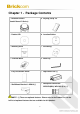
Chapter 1 - Package Contents a. Network Camera b. Dry Bag, Strap Tie (Vandal Dome V2 Series) c. Product CD d. Location Sticker e. Warranty Card f. Screw Bag g. Terminal Block h. Allen Key i. Easy Installation Guide j. High Power PoE (*) k. Wall Mount Bracket: L-WM-01(*) l. Waterproof Connector: WPC-EU(M20)/ WPC-US (3/4’’) (*) NOTE - (*) These are optional features. Please refer to the Product List for the full list of optional features that are available for this product.
Chapter 2 - Vandal Dome Network Camera Overview The VANDAL DOME SERIES is a full-featured, 3-axis, fixed-dome, network camera. With a megapixel progressive sensor and built-in IR-cut filter/ IR illuminator LEDs/ Auto Light sensor, it can provide 24-hour, indoor surveillance. The VANDAL DOME SERIES features a wide-angle and vari-focal lens, which offers wide view coverage of all angles.
5
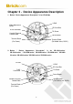
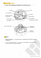
Chapter 3 - Device Appearance Description 1. Below “ Device Appearance Description” is for VD-300Ap LENS Video Adjustment Screw SD Card Slot RJ45 Connector Tilt Screw Conduit Plug and Conduit Hole Reset Button Terminal Block (For Power) Terminal Block (For Audio in/out, DI/DO) 2.
3. Below “ Device Appearance Description” is for VD-501Af-series LENS IR Leds RJ45 Connector Tilt Screw Conduit Plug and Conduit Hole Reset Button Terminal Block (For Audio in/out, DI/DO) Terminal Block (For Power) Focus Control Bar (*) View Angle Control Bar (*) SD/SDHC Card Slot (*) NOTE 1. SD Card Capacity (*) - The network camera is compatible with SD/SDHC (Maximum 32GB) cards. 2. (*) These are optional features.
Chapter 4 - LED Behavior Function LED Behavior Description Power LED Continuous illumination (Green) Power on Power LED Unlit Power off Link LED Continuous illumination (Red) Link Link LED Blinking (Red) Connecting < DI/DO Diagram > 8
< Hardware Reset > Reset Button The Reset Button can be used to reboot the camera or restore it to factory default settings. If the camera experiences a problem, rebooting the camera may correct the problem. If the problem remains, please restore the camera to factory default settings and reinstall the software. To Reboot Press and hold the Reset Button for one second using a paper clip or thin object. Wait for the camera to reboot.
Chapter 5 - Installation 5.1 Hardware Installation a. Remove the vandal dome cover: Use the Allen Key to unscrew the four screws and remove the dome cover from the camera device. b. Open/Close The Conduit Hole: The conduit hole allows the air to circulate through the camera device. By default, a lid is attached to the conduit hole on the side of the camera device, and the conduit hole on the bottom of camera device is open. Please use the screw driver to screw/ unscrew the lid.
c. PoE, Power, DIDO, Audio Connection Put all the cables, such as PoE , 12VDC power , DI / DO / Audio cable , together as one single cable and run it through the waterproof connector. Then attach the waterproof connector to the conduit hole or , and attach the lid tightly to the other hole. All cables are user-supplied.
Terminal Block Pin No. Function Pin No. Function Pin 1 5V Pin 5 Audio OUT Pin 2 D_0 Pin 6 DGND Pin 3 D_I Pin 7 Mic/Line in Pin 4 DIDO GND Pin 8 DGND d. For SD/SDHC Card Installation(Optional): Insert the SD/SDHC card into the SD/SDHC card slot. The SD/SDHC card is not included in the product package and needs to be purchased separately. e. Dry Bag Installation: Open the silver packing of the dry bag, then place the dry bag inside the camera device and secure it using the strap tie. f.
ii. Drill four holes as instruted on the sticker. iii. Hammer the four plastic anchors which are provided in the product package into the four location holes. Mount the camera on the wall and position the four screw holes over the plastic anchors. Insert the screws into the holes and use the screwdriver to tighten the screws clockwise into the holes until they are fixed. g. Mount The Camera To The Ceiling: Mount the camera device on the desired location.
WARNING: Do not mount the camera on any soft material. The camera may fall and be damaged.POE, Power, DIDO, Audio Connection: h. Adjust the Lens (This function applies to all VD series, except the VD-***Nf and VD-***Af.) 1) Adjust The Lens Angle i. The lens holder can be rotated clockwise or counter clockwise. ii. Release the tilt screw on both side of the device to tilt the lens up or down. After completion, tighten the tilt screw. iii.
get the desired field of view. After completion, tighten the zoom ring controller. ii. Release the focus ring controller bar and slide it left or right to make the image in focus. After completion, tighten the focus ring controller. Zoom Ring Controller Focus Ring Controller i. Complete the Installation a. Place the dome cover on the camera device and slowly turn it until it is in the desired position. b. Use the Allen Key to attach the four dome screws to fix the dome cover onto the camera device.
a. Ethernet and DC12V Connection Connect the camera device to the Ethernet switch using an RJ45 Ethernet cable and connect the DC12V power adaptor to the camera device. b. Power over Ethernet (PoE) Connection i. Connect the camera to a PoE switch using a single Ethernet cable. ii. Connect the camera to a non-PoE switch using the PoE Injector. 5.
Operating System: Microsoft Windows XP Home Edition SP2 Microsoft Windows XP Professional SP2 Computer: IBM PC/AT Compatible CPU: Pentium 3GHz or faster Memory: 1024 MB or more Monitor: 1024 x 768 pixels or more, 24-bit True color or better Network Interface: 10/100Mbps Network interface card must be installed Web Browser: Microsoft Internet Explorer 6.0 SP2 or higher Adobe Reader: Adobe Reader 8.0 or higher Audio: The audio function will not work if a sound card is not installed in the PC.
5.4 Software Installation In this manual, "User" refers to whoever has access to the Network Camera, and "Administrator" refers to the person who can configure the camera and grant user access to the camera. After checking the hardware connection, run the Installation Wizard program included on the product’s CDROM to automatically search the intranet for the camera. There may be many cameras on the local network.
B. In the Install Shield Wizard dialog box, click to continue. C. Read the End-User License Agreement and check the option “I accept the terms of the license agreement”. Click to continue.
D. Click to change the appointed folder where installation and program files will be stored. Click to continue. E. Select to create shortcuts. Click to continue.
F. Select the application and click . When launching the PC-NVR program, please refer to the PC-NVR user manual. 5.4.1 EasyConfig To launch EasyConfig, select EasyConfig from the start menu. If Complete Setup type was used in the software installation, an EasyConfig icon was installed on the desktop. Double click to open the icon.
22
B. Select either “Simple Mode” or “Professional Mode” to obtain the camera’s IP settings. If “Simple Mode” is selected, EasyConfig will set up the connection automatically. If “Professional Mode” is selected, the user will need to configure the IP settings manually.
C. There may be many cameras in the local network. Differentiate the cameras using their UPnP name. Double click on the camera from the survey list to connect. D. For configuring the IP address settings, select either , or . The DHCP setting is recommended. E. If is selected, the following pages will be displayed.
25
F. When the IP address settings have been configured, the screen will either display a successful or failed connection message. If the connection failed, either try again or quit the installation. a. If “DHCP IP address settings” was selected, the failure page will be displayed as below: b.
c. If the connection was successful, the user will see the message: “Congratulations. The installation of the camera is complete.” When this window is displayed, click to start the PC-NVR program, to view the live video from the connected IP camera, or in the top right corner of the screen to close the installation window. If the user starts the PC-NVR program, please refer to the PC-NVR user manual. Click to view the live video feed of the network camera.