TM GE60 Installation Manual 3 Installation of E60 products 3.1 General It is recommended that installation personnel read this section in its entirety prior to installing the BridgeWave System. During a particular phase of installation, the user may refer directly to the applicable subsection. The Installation section is comprised of seven subsections covering the procedures and guidelines for installing the BridgeWave Radio System. Subsections 3 through 3.
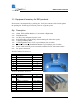
TM GE60 Installation Manual 3.3 Equipment Inventory for E60 products Each carton is accompanied by a packing list. Verify the contents of the carton against the packing list. Following are inventory lists for a typical system. Qty Description 2 ea. 2 ea. 2 ea. 2 ea. 2 ea. 1 ea. 1 ea. 2 ea. 8 ea.
TM GE60 Installation Manual CAUTION! Tampering with seals will void the warranty. Notice the warranty stickers on the inner (metal) cover of the radio. The radio is sealed at the factory. There is no need to open this cover in the field. Tampering with these seals will void the warranty. 3.3.1 Equipment Inventory for E60X products Each carton is accompanied by a packing list. Verify the contents of the carton against the packing list. Following are inventory lists for a typical system.
TM GE60 Installation Manual 3.4 Installation Tools The following tools, not provided by BridgeWave, should be used for installing the radio: Screwdriver, slotted 0.1 inch (2.5mm) wide Open-end wrench 11/32 (9mm) Open-end wrench 9/16 (14mm), 2 ea.
TM GE60 Installation Manual 3.5 Radio Mount Installation E60 products Wall Mounting 1. Install 4 mounting bolts in the wall at the desired location using the template provided (see Figure 3-4 below). The bolts (normally ⅜-16) should extend 0.8 to 3.0 inches (2cm to 7.5cm) from the wall and be strong enough to secure the radio to the wall under foreseeable environmental conditions. The environmental conditions may include, but not limited to, wind, rain, ice, etc.
TM GE60 Installation Manual 3. Attach the radio yoke to the mount, with Teflon shim in-between, using 2 each of the supplied ⅜-16 x ¾ bolts, ⅜ lock washers, and ⅜ flat washers. Tighten the bolts just enough that the yoke can move back and forth without binding. 3/8 Lock Washer 3/8-16x3/4 Bolts 3/8 Flat Washer Mounting Bracket Teflon Shim Radio Yoke Pole Mounting The pole mount kit can be used to secure the mount to a pole with diameters between 2.0 to 4.5 inches (50 to 115 mm). 1.
TM GE60 Installation Manual Figure 3-2: Mount with Radio Yoke in ‘Pole Mount’ Configuration Figure 3-3: Side view of mount in Pole Mount Configuration 580-00507, rev 1 22 of 46
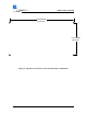
TM GE60 Installation Manual 6.25 inches (15.9 cm) 3.13 inches (8.
TM GE60 Installation Manual 3.5.1 Antenna Mount Installation E60X products WARNING! 1. Read these instructions before beginning installation. Caution should be used. Qualified persons experienced with antenna assembly and installation are required for installation. 2. BridgeWave Communications Inc. disclaims any responsibility or liability for damage or injury resulting from incorrect or unsafe installation practices. 3. The antenna has been formed to a very close tolerance parabolic shape.
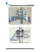
TM GE60 Installation Manual 2. Attach the lower pole mount as shown. Hardware: Flat washer, bushing (inside eye), flat washer, lock washer, bolt. Confirm that the Mount is centered as shown. Tighten bolts securely Figure 3-3.1 and 3-4.
TM GE60 Installation Manual 3. Completed installation of pole mount with right hand offset for the antenna. Note the position of the elevation adjust hex nut. Figure 3-5.1 4. Optional left hand antenna offset mount preparation. - Remove bolts rotate the antenna mounting plate 180º replace bolts tighten bolts securely Note the new position of the elevation adjust hex nut. Figure 3-6.
TM GE60 Installation Manual 3.6 Radio Installation 1. Place the radio in the yoke—the two up/down pivot bolts should rest in the U’s cut in the yoke. Note that when the radio comes from the factory, the mounting plates are in the vertical polarization position, that is, the diamond marking on the radio (see insert below) on the front of the radio housing is to the right when viewed from the front.
TM GE60 Installation Manual 2. Once the radio has been placed in the yoke mount, insert the bolt in the lower portion of the yoke to secure the radio to the yoke. Tighten both the pivot bolts and the lower yoke bolts enough such that the radio is secured in the mount but is still able to be moved back and forth easily. Note: Use both flat washer & split lock washer on lower yoke bolt Figure 3-6: Detail of Radio in Yoke Mount and the Up/Down Pivot Bolt.
TM GE60 Installation Manual 3.6.1 Antenna and Radio installation 5. Install – Antenna Slip antenna over pivot pin, ensuring that the elevation adjust pin is engaged with slot in adaptor plate. Secure the antenna with two (2) x 3/8-16 bolts, lock washer, flat washer and nylon washers attach antenna to the alignment plate. Figure 3-7.
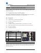
TM GE60 Installation Manual Figure 3-8.1: Polarization diamond orientations: horizontal (right) and vertical (left) Note: The blue color label indicates a high band radio and the red color label indicates a low band radio CAUTION! It is critically important during installation to ensure the radios on each side of the link are in the same polarization (horizontal-horizontal or verticalvertical).
TM GE60 Installation Manual 7. Attach the radio to the back of the antenna and tighten the four (4) bolts. See 6. for details. Figure 3-10.1 Attaching the radio to the back of the antenna 8.Adjust azimuth (Side to Side) 1. Loosen the 4 Azimuth lock bolts 3. Secure the 4 Azimuth lock bolts (tighten until lock washers are flatend) 2. Adjust eyebolt length using a 9/16 open-end wrench to required location Figure 3-11.
TM GE60 Installation Manual Caution! It is very important that the azimuth bolts are tightened before any elevation adjustment is done. The very narrow beamwidth of this antenna (0.6º) makes it necessary to completely tighten the bolts of the azimuth adjustment while adjusting the elevation and vice versa. 8. Adjust elevation (up - down) 2. Rotate Elevation adjust hex nut as required to set correct elevation. 1. Loosen (2) antenna mounting bolts 3. Tighten all bolts after the elevation is set.
TM GE60 Installation Manual 3.7 Cable Installation Fiber Cabling 1. Install a duplex multi-mode fiber from the radio to the network termination equipment (switch or router with 1000Base-SX port). The cable should be looped around the inside of the enclosure to provide strain-relief. Do not connect the fibers to the radio’s fiber ports at this time. The connectors on the radio end of the fiber require simplex LC connectors; the connectors on the switch/router end should mate to the network equipment.
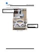
TM GE60 Installation Manual Figure 3-7: Front view of fiber and power cable installed on a vertically polarized E60 unit. Figure 3-8: Inside view of fiber and power cable connected E60 or E60X unit Note: The fiber cable is inserted through the straight through fitting on the left and the power cable is inserted through the fitting on the right.
TM GE60 Installation Manual Ground Cabling The preferred method for grounding the radio unit is to ground the mast (or wall-mount bracket) to a ground source, since this provides the largest grounding surface contact possible. If this is not possible, then use the following procedure: 1. Attach the lug of the copper ground cable provided with the radio to one of the two #8 holes at the bottom of the radio using a #8-32 bolt, #8 lock washer and #8 flat washers. 2.
TM GE60 Installation Manual 3.8 Antenna Alignment E60 systems 1. Place the radio in the mounting bracket, make sure both bolts slide to the bottom of the cutouts. 2. Tighten mounting bolts just enough to allow radio to pivot up/down and right/left with minimal effort. DO NOT CONNECT EITHER THE DC OR FIBER CABLES TO THE RADIO AT THIS POINT! Tilt the radio so that it is roughly points towards the other end of the link. 3.
TM GE60 Installation Manual R a d io a t fa r e n d o f lin k T h e a lig n m e n t a id s n e e d to b e in a s tra ig h t lin e . T a rg e t, o th e r ra d io , is p la c e d a t to p o f m id d le a id . R ig h t Radio at far end of link Aiming Too low Wrong 5. Ensure fiber cables are still disconnected! 6. Connect DC power to the radio. 7. Verify that the Power LED is lit. If the Power LED is not lit, use voltmeter to verify correct voltage and polarity at radio.
TM GE60 Installation Manual 11. Begin to tighten the mounting bolts. It is important to tighten the bolts in the following order. First start with the bolts that control the left/right movement of the radio. These are the bolts on the yoke portion of the mount behind the radio. Start by tightening the bolt closest to the pole or wall. Once this is tightened, move to the bolt directly in front of the bolt you just tightened and slowly tighten this bolt.
TM GE60 Installation Manual 3.8.1 Turning on an E60X system 1. Finish the installation as described in Chapter 3.6 and 3.7 2. Ensure fiber cables are still disconnected! 3. Connect DC power to the radio. 4. Verify that the Power LED is lit. If the Power LED is not lit, use voltmeter to verify correct voltage and polarity at radio. To reverse the power polarity, unplug the power jack and swap the crimp connectors for the two conductors. 5. Repeat steps 1 through 4 on other side of the link. 6.
TM GE60 Installation Manual 11. Once the fiber is connected to the radio, the radio will begin an internal link calibration. During this time the Link Up LED will blink for approximately 30 seconds. 12. Wait until the Link Up LED is lit solid on both radios. 13. Verify the Link Quality voltage is 3.3V (i.e., error free). Repeat steps 10-12 for the second radio. Note: When a radio is power cycled and it’s fiber cable disconnected, it will reexecute the calibration process.
TM GE60 Installation Manual Auto Calibration States State Unit powered up no fiber connected Unit powered up and fiber cable connected Normal operation mode Forced Recalibration Description Unit will be in alignment mode, there will be no automatic calibration event started until the fiber is connected The radio will perform a single calibration scan and will then go into normal operation mode, regardless of the results of the scan.
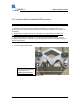
TM GE60 Installation Manual Figure 3-10: Top view of test cable provided to check Link Quality & Receive Signal level 2. To read the Link Quality value of the radio, insert GND (ground) and QUAL banana plugs into the voltmeter. Note the Link Quality voltage. After the radios have performed an auto calibration the quality voltage should read 3.3v if the link is aligned on the main antenna beam and there are no obstructions (i.e.
TM GE60 Installation Manual 4 Operation of E60, E60X radios & configuration of network equipment The E60 product line has been designed such that it requires no user configuration. During normal operation, the following conditions should exist at the radio: 1 2 3 4 The power LED should be lit—solid green; The fiber LED should be lit—solid green; The Link Up LED should be lit—solid green; and The Link Quality BER voltage should be 3.
TM GE60 Installation Manual 4.1 Configuring Network Equipment The networking equipment that is connected to an E60 product should first be checked to ensure it operates properly over a wired connection. Once this has been confirmed this will save troubleshooting steps after the radio is installed and connected to the network equipment.
TM GE60 Installation Manual 5 Troubleshooting The following table provides a summary of possible problems you might encounter while installing a BridgeWave GE60 link, along with possible causes and their solutions. Problem No power to radio Possible Cause Wrong polarity of supply voltage The supply voltage measured at the radio (when connected) is below 15Vdc Fiber light lit at radio but not on network equipment Radio link is down and/or fiber not connected between remote radio and network equipment.
TM GE60 Installation Manual RSL voltage lower then expected Incorrect calculation of link distance Antennas aligned on side lobes Antennas set to different polarizations Installed two high or low band radios in one link Low link quality voltage Link exceeds maximum specified range Fibers are not connected Antennas are not aligned for maximum RSL Auto calibration not completed Interference 580-00507, rev 1 46 of 46 Verify that the calculation tool used and the GPS used both use the same annotation s