* For pricing and a quotation, visit MeridianMicrowave.com TM GE/AR80 Installation Manual making connections in a high-speed world Wireless Gigabit Ethernet Links Models GE80 and AR80 Installation Manual P/N 580-00519 Revision A September 2006 580-00519, rev A 1 of 40 * For pricing and a quotation, visit MeridianMicrowave.
* For pricing and a quotation, visit MeridianMicrowave.com TM GE/AR80 Installation Manual Copyright Notice & Disclaimer Copyright © 2004-2006 BridgeWave Communications. All rights reserved. Printed in the USA No portion of this publication may be reproduced, copied, or distributed without the written consent of BridgeWave Communications. BridgeWave reserves the right to update or change the material in this publication at any time without notice.
* For pricing and a quotation, visit MeridianMicrowave.com TM GE/AR80 Installation Manual Product Compatibility While every effort has been made to verify operation of this product with many different communications products and networks, BridgeWave makes no claim of compatibility between its products and other vendors’ equipment. Customer is responsible for thoroughly evaluated this product’s performance in the communications environment in which it will be used.
* For pricing and a quotation, visit MeridianMicrowave.com TM GE/AR80 Installation Manual Regulatory Information This device complies with Part 101 of the FCC Rules. Links installed in the U.S. must be registered with the FCC as provided for in Part 101 of the FCC regulations. For more information contact BridgeWave’s Customer Service via E-mail support@bridgewave.com or call at 408-567-6906.
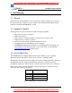
* For pricing and a quotation, visit MeridianMicrowave.com TM GE/AR80 Installation Manual Table of Contents Section# Copyright Notice & Disclaimer Product Compatibility Safety Regulatory Information Equipment Precautions Table of Contents 1 Introduction 1.1 Purpose of Manual 1.2 Prior Knowledge and Manual Conventions 1.3 Contact Information & RMA 2 Site Planning 2.1 General 2.2 Equipment Checklist 2.3 Line of Sight 2.4 Link Distance 2.5 Antenna Location 2.6 Cabling 2.
* For pricing and a quotation, visit MeridianMicrowave.com TM GE/AR80 Installation Manual 1 Introduction 1.1 Purpose of Manual The information in this manual is directed to persons who must perform or coordinate the tasks associated with the process of installing wireless communication devices, and planning communication network applications. 1.
* For pricing and a quotation, visit MeridianMicrowave.com TM GE/AR80 Installation Manual 1.3 Contact Information Technical Assistance and Customer Service BridgeWave distributors and resellers are authorized local service providers and are responsible for immediate Tier 1 customer support. If problems are not resolved, contact BridgeWave Customer Service for assistance: Location: E-mail: Tech Support Hot Line: Santa Clara, CA USA support@bridgewave.com +1.408.567.
* For pricing and a quotation, visit MeridianMicrowave.com TM GE/AR80 Installation Manual 2 Site Planning 2.1 General Before the start of an installation a survey should be conducted of the proposed area of the deployment site(s). The survey personnel should be fully familiar with the details required to install the GE/AR80 radio system. 2.
* For pricing and a quotation, visit MeridianMicrowave.com TM GE/AR80 Installation Manual 2.4 Link Distance Measurement of the link distance is important in estimating the link availability and calculating expected Receive Signal Level (RSL). This measurement can be performed using the Latitude and Longitude coordinate readings from a Global Positioning System (GPS) device, which is placed near the proposed locations of the antennas.
* For pricing and a quotation, visit MeridianMicrowave.com TM GE/AR80 Installation Manual The radio requires LC type connectors on a pair of simplex multi-mode fibers to properly connect between the radio and the users network equipment. Single-mode fiber connections are not supported for use with the standard product. The network equipment end of the fibers should be terminated with connectors that match the user’s network equipment fiber interface. Fiber Cable Length Cable Type Up to 270 meters 62.
* For pricing and a quotation, visit MeridianMicrowave.com TM GE/AR80 Installation Manual Figure 2-4: 14-gauge DC power cable terminated to radio end and power supply end. Figure 2-4 (right) details a standard 14-gauge wire that has been fitted with the power connectors (provided) for the radio’s internal power supply necessary to mate with the (not provided) power cord.
* For pricing and a quotation, visit MeridianMicrowave.com TM GE/AR80 Installation Manual 2.7 Grounding & Lightning Protection WARNING! Proper grounding of the outdoor equipment reduces electromagnetic interference, provides surge protection, and protects against electrical discharge. The source and connection points for the building-to-earth ground in the vicinity of the antenna location should be determined.
* For pricing and a quotation, visit MeridianMicrowave.com TM GE/AR80 Installation Manual 2.8 Environmental The structure to which the equipment will be mounted should be adequate to bear all wind and weather conditions. The environmental conditions at the location must conform to the operating environment specified for the equipment. 2.9 Simple Network Diagram Following is a diagram detailing the equipment and cabling found on a typical installation of BridgeWave’s 80GHz radio equipment.
* For pricing and a quotation, visit MeridianMicrowave.com TM GE/AR80 Installation Manual 3 Installation 3.1 General It is recommended that installation personnel read this section in its entirety prior to installing the BridgeWave System. During a particular phase of installation, the user may refer directly to the applicable subsection. The Installation section is comprised of seven subsections covering the procedures and guidelines for installing the BridgeWave Radio System. Subsections 3 through 3.
* For pricing and a quotation, visit MeridianMicrowave.com TM GE/AR80 Installation Manual 3.3 Equipment Inventory Following are inventory lists for a typical system: Qty Description 2 ea. GE80 radio units (1 low band transmit unit & 1 high band transmit unit) 2 ea. AC-DC power adapters & power cords 1 ea. CD-ROM containing Installation Manual and NMS Manual (1 CD provided per pair of radios) 2 ea. DC power connectors for use with outdoor radio 4 ea.
* For pricing and a quotation, visit MeridianMicrowave.com TM GE/AR80 Installation Manual CAUTION! Tampering with seals will void the warranty. Notice the warranty stickers on the inner (metal) cover of the radio. The radio is sealed at the factory. There is no need to open this cover in the field. Tampering with these seals will void the warranty. 3.4 Installation Tools The following tools, not provided by BridgeWave, are required for installing the radio and the antenna: Screwdriver, slotted 0.
* For pricing and a quotation, visit MeridianMicrowave.com TM GE/AR80 Installation Manual 3.5 Antenna Mount Installation WARNING! 1. Read these instructions before beginning installation. Caution should be used. Qualified persons experienced with antenna assembly and installation are required for installation. 2. BridgeWave Communications Inc. disclaims any responsibility or liability for damage or injury resulting from incorrect or unsafe installation practices. 3.
* For pricing and a quotation, visit MeridianMicrowave.com TM GE/AR80 Installation Manual 2. Attach the lower pole mount as shown. Hardware: Flat washer, bushing (inside eye), flat washer, lock washer, bolt. Confirm that the Mount is centered as shown. Tighten bolts securely Figure 3-3 and 3-4 580-00519, rev A 18 of 40 * For pricing and a quotation, visit MeridianMicrowave.
* For pricing and a quotation, visit MeridianMicrowave.com TM GE/AR80 Installation Manual 3. Completed installation of pole mount with right hand offset for the antenna. Note the position of the elevation adjust hex nut. Figure 3-5 4. Optional left hand antenna offset mount preparation. - Remove bolts Rotate the antenna mounting plate 180º Replace bolts Tighten bolts securely Note the new position of the elevation adjust hex nut.
* For pricing and a quotation, visit MeridianMicrowave.com TM GE/AR80 Installation Manual 3.6 Antenna and Radio Installation 1. Install – Antenna and Radio Captive bolts Figures 3-7 and 3-8: The first letter of the designated Polarization is stamped onto each unit to identify orientations when the polarity mark is positioned on top: illustrations above are for Horizontal (left) and Vertical polarity right).
* For pricing and a quotation, visit MeridianMicrowave.com TM GE/AR80 Installation Manual 1. Loosen the 4 Azimuth lock bolts 3. Secure the 4 Azimuth lock bolts (tighten until lock washers are flattened) 2. Adjust eyebolt length using a 9/16 open-end wrench to required location Figure 3-9 Azimuth adjustments bolts detail CAUTION! It is very important that the azimuth bolts are tightened before any elevation adjustment is done. The very narrow beamwidth of this antenna (0.
* For pricing and a quotation, visit MeridianMicrowave.com TM GE/AR80 Installation Manual 4. Adjust elevation (up - down) 2. Rotate Elevation adjust hex nut as required to set correct elevation. Caution: Do not try to adjust this bolt with out first loosening up the antenna bolts (Step 1). Doing so may damage the elevation adjustment pin. 1. Loosen (2) antenna mounting bolts 3. Tighten all bolts after the elevation is set.
* For pricing and a quotation, visit MeridianMicrowave.com TM GE/AR80 Installation Manual 3.7 Cable Installation Fiber Cabling 1. Install a duplex multi-mode fiber from the radio to the network termination equipment (switch or router with 1000Base-SX port). The cable should be looped around the inside of the enclosure to provide strain-relief. Do not connect the fibers to the radio’s fiber ports at this time.
* For pricing and a quotation, visit MeridianMicrowave.com TM GE/AR80 Installation Manual Figure 3-11: Back view of fiber and power cable installed on a vertically polarized unit. Notice that the cable conduit is on the left hand side when the radio is in (V) polarization. Figure 3-12: Inside view of fiber and power cable connected 580-00519, rev A 24 of 40 * For pricing and a quotation, visit MeridianMicrowave.
* For pricing and a quotation, visit MeridianMicrowave.com TM GE/AR80 Installation Manual Note: The fiber and power cables are inserted through the straight through fitting, before the conduit is connected to the fitting. Ensure that the cables do not get pinched when the conduit is pushed onto the fitting. Both cables have been looped around the inside of the enclosure to minimize tension on the cables when connected to the radio and to maintain proper bend-radius of the fiber cable.
* For pricing and a quotation, visit MeridianMicrowave.com TM GE/AR80 Installation Manual 3.8 Turning the System On and Alignment 1) Before Turning On the System a) Finish the installation as described in Chapter 3.6 and 3.7 b) Ensure fiber cables are still disconnected! c) Connect DC power to the radio. d) Verify that the Power LED is lit. If the Power LED is not lit, use voltmeter to verify correct voltage and polarity at radio.
* For pricing and a quotation, visit MeridianMicrowave.com TM GE/AR80 Installation Manual d) Loosen the two vertical control bolts holding the antenna to the antenna mount e) The Vertical Fine adjustment is not designed to be tightened; use the “hex nut” to fine (and rough) adjust the elevation (vertical position) to highest RSL value. f) While monitoring the Voltmeter, begin to align the Vertical position of the antenna to obtain the highest RSL voltage level.
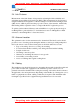
* For pricing and a quotation, visit MeridianMicrowave.com TM GE/AR80 Installation Manual Figure 3-14: The illustration below is an exaggerated cross section of a beam to exemplify a horizontal RSL level voltage reading against relative locations with an assumed fine tuned vertical position. Illustration of a main beam Main Beam 0.
* For pricing and a quotation, visit MeridianMicrowave.com TM GE/AR80 Installation Manual c) Always evenly tighten bolts in small fractions at a time to ensure minimum change to your completed alignment. 6) Connecting the Fiber a) Connect the fiber cable to one of the radios at a time. The fibers should already be connected to active network equipment.
* For pricing and a quotation, visit MeridianMicrowave.com TM GE/AR80 Installation Manual Losing RF connectivity When a system loses the RF connection for more than 5 minutes it will trigger the system to enter an Auto Calibration mode. You can disable this function on the AR80 units via the NMS. Please review the NMS Manual for further details on disabling this function. Force Calibration You can induce a force calibration at anytime by disconnecting DC power and fiber optic cables from the radio.
* For pricing and a quotation, visit MeridianMicrowave.com TM GE/AR80 Installation Manual 3.10 Test Cable The alignment procedure is optimized through the use of the provided test cable. This test cable is designed for use with a digital voltmeter (not provided) to read the Link Quality and Receive Signal Level (RSL) voltage generated by the radio’s receiver. 1. To read the RSL value of the radio, insert GND (ground) and RSL banana plugs into the voltmeter. Note the RSL voltage.
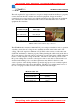
* For pricing and a quotation, visit MeridianMicrowave.com TM GE/AR80 Installation Manual 3.3 Correctable Errors Detected QUAL Voltage (V) 3.0 NO ERRORS 1.5 Uncorrectable Errors Detected CORRECTED ERRORS (PRE-FEC ) 1.0 0.5 UNCORRECTED ERRORS (POST-FEC) 0 0 0 Deframer Unlocked Errors Figure 3-16 Quality Voltage Graph • Quality Voltages between 3.0V and 3.3V indicate an error-free wireless link. • Quality Voltages between 1.5V and 3.
* For pricing and a quotation, visit MeridianMicrowave.com TM GE/AR80 Installation Manual 4 Operation of GE/AR80 & configuration of network equipment During normal operation, the following conditions should exist at the radio: 1 2 3 4 The power LED should be lit—solid green; The fiber LED should be lit—solid green; The Link Up LED should be lit—solid green; and The Link Quality BER voltage normally should be 3.0-3.3v when it is not raining.
* For pricing and a quotation, visit MeridianMicrowave.com TM GE/AR80 Installation Manual 4.1 Configuring Network Equipment The networking equipment that is connected to the GE/AR80 should be checked to ensure it operates properly over a wired connection. Once this has been confirmed it will save troubleshooting steps after the radio is installed and connected to the network equipment.
* For pricing and a quotation, visit MeridianMicrowave.com TM GE/AR80 Installation Manual 5 Troubleshooting The following table provides a summary of possible problems you might encounter while installing a BridgeWave GE/AR80 link, along with possible causes and their solutions.
* For pricing and a quotation, visit MeridianMicrowave.com TM GE/AR80 Installation Manual RSL voltage lower then expected Low link quality voltage 580-00519, rev A Incorrect calculation of link distance Verify that the calculation tool used and the GPS used both have the same annotation system (degree hours minutes seconds or degree with a decimal value) Antennas aligned on side Realign antenna to main lobe. lobes Keep in mind that the first side lobe is only 1 degree from the main lobe.
* For pricing and a quotation, visit MeridianMicrowave.com TM GE/AR80 Installation Manual 6 RSL Vs Distance Chart Note: Readings for path distances below one (1) Kilometer should expect RSL level of 3.3Vdc. 580-00519, rev A 37 of 40 * For pricing and a quotation, visit MeridianMicrowave.
* For pricing and a quotation, visit MeridianMicrowave.com TM GE/AR80 Installation Manual 7 Standard Limited Warranty and Software License THE FOLLOWING WARRANTY AND SOFTWARE LICENSE GRANT APPLY ONLY FOR BRIDGEWAVE COMMUNICATIONS, INC. (“BRIDGEWAVE”) PRODUCTS PURCHASED THROUGH BRIDGEWAVE AUTHORIZED CHANNEL PARTNERS WITHIN THE UNITED STATES OR CANADA BY THE ORIGINAL END PURCHASER (“BUYER”).
* For pricing and a quotation, visit MeridianMicrowave.com TM GE/AR80 Installation Manual JURISDICTION. THIS DISCLAIMER AND EXCLUSION SHALL APPLY EVEN IF THE EXPRESS WARRANTY SET FORTH ABOVE FAILS OF ITS ESSENTIAL PURPOSE. SOFTWARE LICENSE Software License. BridgeWave provides Buyer a non-exclusive, non-transferable limited license (“License”) to use, solely as embedded in, for execution on or for communication with the Products, the object code (and not the source code) of its Software.
* For pricing and a quotation, visit MeridianMicrowave.com TM GE/AR80 Installation Manual Administrative Provisions. This Limited Hardware Warranty and Software License shall be governed by and construed in accordance with the laws of the State of California, without reference to principles of conflict of laws, provided that for customers located in a member state of the European Union, Norway or Switzerland, English law shall apply.