BS-9100 / BS-9100T Backsense® CAN Radar Object Detection System Installation & Operating Guide Installation Guide 7059
Table of Contents 1 Introduction ...................................................................................................................... 3 1.1 Detection Range ..................................................................................................... 3 1.2 Object Detection Capability ..................................................................................... 3 2 Contents.....................................................................................................
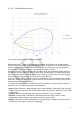
1 Introduction Brigade’s Backsense® uses FMCW (Frequency Modulated Continuous Wave) radar system technology and is designed to detect people and objects in blind spots, significantly reducing collisions. Backsense® detects both stationary and moving objects and works effectively in harsh environments with poor visibility including darkness, smoke, fog and dust.
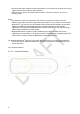
• An object will cause a detection data transmission in less than 0.15 seconds (for moving objects) and 0.25 seconds (for static objects). • After turning on power the system takes around 1 second to be active. There is no standby mode. Notes: • For distances below 1.3m (detection with relative speed only) or below 0.3m (no detection) the space covered in general by radar systems is very small.
1.2.1.2 Vertical Detection Area 1.2.2 Factors Influencing the Detection of Objects Brigade Backsense® shares in principle the advantages and limitations of all radar-based systems when compared to other sensing technologies. In general, it can reliably detect most objects in most environmental conditions such as dirt, dust, rain, snow, sun, fog, darkness, acoustic noise, mechanical vibration, electromagnetic noise or similar. However, there are some occasions when an object could stay undetected.
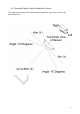
• Angle: An object facing directly towards the sensor (perpendicular, orientation head on to the sensor) is detected better than an object that is located towards the edges of the detection area or at an angle. • Distance: An object closer to the sensor is better detected than one that it is further away. • Relative speed to sensor: Detection is better if there is a relative speed between object and sensor.
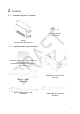
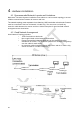
2 2.1 Contents Standard System Contents 4x Sensor Fixing Kit BS-FIX-02 Sensor BS-9100-S or BS-9100T-S 2.
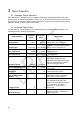
3 Object Detection 3.1 Separate Object Detection Each Backsense® BS-9100 sensor is capable of detecting and reporting data for up to 16 objects within the limitations detailed in section 1.2. In the event that there are more than 16 objects within the detection area of a particular sensor, only the closest 16 detections will be reported, (based on object radius from sensor) 3.2 Detected Object Data The BS-9100 will transmit data for each detected object in separate CAN messages.
3.
4 Hardware Installation 4.1 Recommended Network Layouts and Limitations Backsense® BS-9100 Systems installation must adhere to a strict network topology to ensure reliable communications between all sensors and host. The network topology must represent a bus featuring 120Ω termination at both ends. Sensors must be connected to the bus via Network Y-Cable only. The user must not install any extension cable between the sensor and the Y-Cable.
4.3 Bad Network Arrangement Bad Network Topology may include: o Long bus length >30m. o Non-bus configuration (e.g. star, mesh etc.). o Power at one end only (resulting in possible voltage drop in cable). o Termination missing at both ends of network. o Omission of Network Terminator cable. o Extension cable between sensor and Y-Cable. o Connection to more than 8 sensors on single bus. o Connection to other CAN nodes, (not shown below). Example 3 (Bad), host connection at end of bus. 4.
4.5.2 Sensor Fixing Each unit is supplied with four M5x30mm screws and four M5 polymer locknuts for mounting purposes. The recommended torque is 6Nm or 50 inch/lbs. 4.5.3 Vehicle Overhang into Detection Area The vehicle mounting locations should avoid detection of any overhang or vehicle ancillary equipment where possible. Such objects will cause false detections (for exceptions see section “1.2 Object Detection Capability”, paragraph “Warning”).
4.7 Electrical Connections Refer to the vehicle manufacturer or bodybuilder guidelines for installation procedures and connectivity in all applications. The sensor pinout is shown in the table below and connector details given in section9: Deutsch Pin Signal Name Brigade Wire Colour 1 Ground Brown 2 CAN High Green 3 Positive (+12/+24V) Yellow 4 CAN Low Blue 4.8 Power Input Power must be applied to the BS-9100 sensor network via a dedicated Brigade power cable.
4.9 Recommended Fuse Values Supply Voltage Network Size (Number of Sensors) Power Consumption Steady State Current Inrush Current Recommended Fuse Value 1 2.8W 0.23A <0.85A, <20mSec 1A 2 5.6W 0.46A 1A 3 8.4W 0.69A 1A 4 10.7W 0.92A 2A 5 13W 1.15A 2A 6 15.3W 1.38A 2A 7 17.6W 1.61A 2A 8 19.9W 1.84A 3A 1 2.9W 0.12A 2 5.8W 0.24A 1A 3 8.7W 0.36A 1A 4 11.6W 0.48A 1A 5 14.5W 0.6A 1A 6 17.4W 0.72A 1A 7 20.3W 0.84A 2A 8 23.2W 0.
5 CAN Bus 5.1 Network Parameters The BS-9100 system must operate on an independent CAN bus with no other connections apart from power, terminations and typically one customer-supplied host. CAN communications parameters from the sensor network are detailed below: • • • • • • • • Complies with CAN 2.
5.4 Base ID Configuration Systems installers may configure sensor base ID values using their own host system, or by use of the Brigade Test tool detailed in section 7. Each BS-9100 sensor within a network must be configured with an individual Base ID. The method for Base ID configuration is simple and involves sending a single configuration message to each individual sensor in the CAN network, using a specific “Configuration ID” for that sensor. The procedure is as follows: 1. 2. 3. 4. 5. 6.
5.
Object 14th Closest Object 15th Closest Object 16th Closest Object 0x31D 0x32D 0x33D 0x34D 0x35D 0x36D 0x37D 0x38D 0x31E 0x32E 0x33E 0x34E 0x35E 0x36E 0x37E 0x38E 0x31F 0x32F 0x33F 0x34F 0x35F 0x36F 0x37F 0x38F 5.7 Detection Message Detection data for each detected object (per sensor) is reported in a single CAN message from the sensor with a message as detailed in section 3.2.
Sensor Error 3 7 6 1 N/A N/A 0 1 N/A N/A 7 5 1 N/A N/A 0 1 N/A N/A 0 = No Error 1 = Voltage Error 7 4 1 N/A N/A 0 1 N/A N/A Not used 7 2 2 N/A N/A N/A N/A N/A N/A 7 1 1 N/A N/A 0 1 N/A N/A 7 0 1 0 1 0 1 0x00 0x01 0 = No Error 1 = Temperature Error (>135°C) Sensor Error 2 0 = No Error 1 = MMIC Error Sensor Error 1 Identification Flag 0 = BS-9000 1 = 77GHz Radar Detection Flag 0 = Valid detection 1 = No detection 5.
6 System Host 6.1 Host Responsibilities BS-9100 systems require connection to a customer-supplied host to receive and utilise object detection messages from the sensor via CAN bus. The host system is responsible for interpreting the detection data detailed in section 5.7 and applying any logic, conditioning, filtering, activation or blind zone settings (e.g. ignoring certain detection under pre-determined conditions) that may be required in the application of the system.
7 Brigade Backsense CAN Radar Test Tool 7.1 PC Interface for BS-9100 As detailed in section 5, the Brigade BS-9100 radar sensors use CAN for all communications to the host system, including configuration and test activities. The Brigade Backsense Test Tool cannot be run without the Sfting Interface being plugged into the PC.
7.4 Software Installation 7.4.1 Softing CAN Drivers and Software installation Once the driver installation file has been downloaded from www.softing.com it should be installed as per standard practice. Screen views of the process are shown below (Note: Layout may vary depending on Softing software version).
The application can now be launched from the Start Menu under the heading Softing CAN. 7.4.2 Softing CAN Drivers and Software configuration Once the setup has been completed, the Softing CAN Interface Manager should be launched. Once the CAN interface has been connected to the PC, the Softing Interface Manager should automatically detect and list it as a device. The following steps should then be performed to configure the interface for use with the Brigade Backsense CAN Radar Test Tool.
7.4.3 Backsense CAN Radar Test Tool installation Once the driver installation file has been downloaded from www.brigade-electronics.com t should be installed as per standard practice. Screen views of the process are shown below (Note: Layout may vary depending on version).
7.5 Backsense CAN Radar Test Tool The Brigade test tool is a windows application that enables users to view all physical detection data from the radar system in real time. The test tool consists of a main Graphic & Control Window displaying a top-down view of detected objects for one selected sensor as well as a sub window for that sensor’s detection data and another sub window displaying detected object positions for all sensors in the network.
Graphic and Control Window displaying six detected objects for sensor 1 (CAN ID 0x310). 7.5.2 Backsense Detection Table The Backsense Detection Table is a floating sub window of the Graphic and Control window which displays numerical values for all detection data of up to 16 closest objects detected by the selected sensor. There is no user interaction available for the Backsense Detection Table.
7.6.1 The Backsense Configuration Tool may be launched from the “Tools” menu within the Backsense CAN Radar Test Tool, as shown below: 7.6.2 Depending on PC security settings, the following warning may be seen.
7.6.3 The launch screen of the Backsense Configuration Tool will appear as below. The connected CANpro interface is identified by serial number.
7.6.4 The Initialisation screen of the Backsense Configuration Tool will appear as below. Command options are displayed on the screen: The Configuration Tool Command Options are as follows: ▪ h o Display help menu – Configuration Tool Command Options will be redisplayed. ▪ r ➢ Monitor CAN Bus Data – Allows the user to view all CAN data that appears on the bus. ▪ Space Bar ➢ Pause live view of CAN Bus Data.
7.6.5 The user may start (or re-start) monitoring of live CAN data from the sensor (or entire Backsense network) by pressing the “R” key on the keyboard. Spacebar may be used to pause live CAN data. 7.6.6 The description for Configuration Tool data is as illustrated below: RCV = “Received Data” STD = “Standard Frame” CAN1 = CANpro Channel No.
DLC8 = Data Length Code is 8 Bytes Data XX XX XX XX XX XX XX XX= Detection Data in Hex format from sensor T 1372a292 = Timestamp from launch of CAN driver (Hex uSec) 32 D 230 = Delta time since previous message (Dec uSec)
7.6.7 Pressing the “S” key on the keyboard will enter sensor ID configuration function as shown below: User presses S key to enter Selection menu of configuration function 7.6.8 The user must select the sensor to be configured by pressing the number of that sensor on the keyboard. In the example below, only one sensor with Sensor ID 0x09 is connected, (as identified by “390” CAN data). In this instance the user will press “9” on the keyboard.
7.6.9 To re-configure the sensor ID, the user must press “C” on the keyboard as below: User presses C key to enter Change menu of configuration function 1 7.6.10 The user must select the number for the desired sensor ID.
7.6.11 Now reset the radar (power cycle). 7.6.12 The user may check for correct ID change by monitor live CAN data from the sensor Pressing the “r” key on the keyboard will start monitoring. 7.6.13 The Backsense Configuration Tool must be closed in order to return to the Backsense CAN Radar Test Tool. 7.7 Application Errors 7.7.
The Brigade Backsense® System cannot self-diagnose potential sensor detection issues caused by the build-up of ice, dirt, mud, heavy rain or immersion in water, which may impede system performance. Therefore, follow section “8 Testing and Maintenance”.
8 Testing and Maintenance 8.1 Operator Instructions This information is addressed to the operator of the vehicle where a Brigade Backsense ® System is installed: 1) The Brigade Backsense® is intended as an Object Detection System and should not be relied upon as your primary defence for the safe operation of the vehicle. It is an aid to contribute in conjunction with other established safety programs and procedures to ensure safe operation of the vehicle in relation to surrounding persons and objects.
For the following tests, the operator requires objects to be placed in the sensor’s detection areas or an assistant (to observe the host activity). 5) Verify each accuracy of detection distance: Starting from the outside of the detection area, the operator should check several points along the centre line of the detection width down to around 0.4m distance from each sensor.
9 Specifications Operation Characteristics Model name Detection length Detection width Nominal tolerance Radar beam angle Distance resolution Object detection BS-9100 60m (197 ft approx.) 16m (52ft approx.) ±0.25m / (1ft approx.) Horizontal 140° out to the maximum designated width Vertical 12° (symmetrically perpendicular to sensor front surface) 0.25m (1ft approx.). Limitations apply, see section “1.2 Object Detection Capability” for details. ≤ 0.15second (for moving objects) ≤0.
Electrical Specification Input Voltage Range Input Current (per sensor) Power Supply Fusing Vehicle Connections Host Connections Voltage Protection 9 to 32 Vdc typ. 0.23A at 12Vdc / typ. 0.12A at 24Vdc Dependent upon number of sensors in network. See section 4.9 for details System supply positive & negative.
10 Mounting Dimensions 41
11 Disclaimer Disclaimer Radar obstacle detection systems are an invaluable driver aid but do not exempt the driver from taking every normal precaution when conducting a manoeuvre. No liability arising out of the use or failure of the product can in any way be attached to Brigade or to the distributor. Avertissement Les systèmes de radar à détection d'obstacle sont une aide précieuse pour le conducteur, mais celui-ci doit toutefois prendre toutes les précautions nécessaires pendant les manœuvres.
Specifications subject to change. Sous réserve de modifications techniques. Ä nderungen der technischen Daten vorbehalten. Specifiche soggette a variazioni. Las especificaciones están sujetas a cambios. Wijzigingen in specificaties voorbehouden. As especificações estão sujeitas a alterações. Спецификация может изменяться. Specyfikacja techniczna może ulec zmianie. Ö zellikler haber vermeksizin değiştirilebilir. Serial No: Part No: BS-9100(xxxx)-InstallationOperation Guide - ENG - draft.