Generator Systems N o R tf ep o r ro du ct io n Operator’s Manual Home Generator System
Thank you for purchasing this quality-built Briggs & Stratton home generator. We’re pleased that you’ve placed your confidence in the Briggs & Stratton brand. When operated and maintained according to the instructions in this manual, your home generator will provide many years of dependable service. This manual contains safety information to make you aware of the hazards and risks associated with home standby generators and how to avoid them.
Table of Contents Important Safety Instructions . . . . . . . . . . . . . . . . . . . . . . . . 4 Installation . . . . . . . . . . . . . . . . . . . . . . . . . . . . . . . . . . . . . 7 Owner Orientation . . . . . . . . . . . . . . . . . . . . . . . . . . . . . . . . . . . . . . . . . . . . 7 Fuel Factors . . . . . . . . . . . . . . . . . . . . . . . . . . . . . . . . . . . . . . . . . . . . . . . . . 8 Delivery Inspection . . . . . . . . . . . . . . . . . . . . . . . . . . . . . . . . . . . . . . . . .
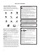
Save These Instructions Important Safety Instructions SAVE THESE INSTRUCTIONS - This manual contains important instructions that should be followed during installation and maintenance of the generator and batteries. Safety Symbols and Meanings Explosion Fire Electrical Shock Toxic Fumes Rotating Parts Hot Surface WARNING Running engine gives off carbon monoxide, an odorless, colorless, poison gas.
• • • • • • • • • • • • • • n • • • WARNING Propane and Natural Gas are extremely flammable and explosive, which could cause burns, fire or explosion resulting in death, serious injury and/or property damage. DO NOT operate the equipment if the “fuel shut-off” valve is missing or inoperative. Install the fuel supply system according to NFPA 37 and other applicable fuel-gas codes. Before placing the generator into service, the fuel system lines must be properly purged and leak tested.
• • • • • • • CAUTION Installing the 15A fuse could cause the engine to start at any time without warning resulting in minor or moderate injury. • Observe that the 15 Amp fuse has been removed from the control panel for shipping. • DO NOT install this fuse until all plumbing and wiring has been completed and inspected. 6 NOTICE Improper treatment of generator can damage it and shorten its life. • Use generator only for intended uses.
Installation For the Home Owner: Only current licensed electrical and plumbing professionals should attempt home generator system installations. Installations must strictly comply with all applicable codes, industry standards and regulations. Your home generator is supplied with this “Operator’s Manual” and a separate “Installation Manual”. These are important documents and should be retained by the owner after the installation has been completed.
Fuel Factors N o R tf ep o r ro du ct io An important consideration affecting the entire installation is the type of fuel used by your generator. The system was factory tested and adjusted using either natural gas or liquid propane (LP vapor).
A WARNING Running engine gives off carbon monoxide, an odorless, colorless, poison gas. Breathing carbon monoxide could result in death, serious injury, headache, fatigue, dizziness, vomiting, confusion, seizures, nausea or fainting. • Operate this product ONLY outdoors in an area that will not accumulate deadly exhaust gas.
Delivery Inspection Carefully inspect the generator for any damage that may have occurred during shipment. If loss or damage is noted at time of delivery, have the person(s) making delivery note all damage on the freight bill and affix his signature under the consignor’s memo of loss or damage. If loss or damage is noted after delivery, separate the damaged materials and contact the carrier and your installer for claim procedures. Missing or damaged parts are not warranted.
Controls 15kW, 16kW and 20kW Generator (Front View) Read this Operator’s Manual and Important Safety Instructions before operating your generator. Compare the illustrations with your generator to familiarize yourself with the locations of various controls and adjustments. Save this manual for future reference. D E F C G B A N o R tf ep o r ro du ct io n H Generator is shown with roof and access covers removed for clarity. A - Lifting Holes — Provided at each corner for lifting generator.
15kW, 16kW and 20kW Generator (Back View) Read this Operator’s Manual and Important Safety Instructions before operating your generator. Compare the illustrations with your generator to familiarize yourself with the locations of various controls and adjustments. Save this manual for future reference. G H F J D C B A N o R tf ep o r ro du ct io n E Generator is shown with roof and access covers removed for clarity. A - Lifting Holes — Provided at each corner for lifting generator.
Access Panels The generator is equipped with an enclosure that has several access panels, as shown.
To open roof: 1. Insert key into lock (A) of front panel. Gently push down on roof above the lock to aid in turning the key. Turn key one quarter turn clockwise. 2. Lift roof to the open position. To remove rear panel: 1. Ensure the roof is in the open position. 2. Remove the two bolts (C) that secure the panel to the unit. C To remove front panel: 1. Remove the two bolts (B) that secure the panel to the unit. 2. Lift panel to remove from unit. B 3. Lift panel to remove from unit.
System Control Panel Compare this control panel illustration with your generator to familiarize yourself with the location of these important controls: F MENU A ESC E D N o R tf ep o r ro du ct io n B AUTO C OFF A - Menu/Programming Navigation Buttons — See Menu section for details B - Mini USB Port — Authorized Dealer Service Use Only C - Generator Operation Control Buttons — •“AUTO” Normal operating position. Press and hold button to put unit into Automatic mode.
Menu The following chart shows the icons for the buttons that control the system control panel. ENTER THE MENU (VIEW SETTINGS) PRESS TO CONFIRM SELECTION WHEN PROGRAMMING. MENU ESCAPE (EXIT) RETURN TO LAST MENU ITEM RIGHT ARROW TOGGLE THROUGH MENU OPTIONS SETTING SYSTEM PARAMETERS LEFT ARROW TOGGLE THROUGH MENU OPTIONS SETTING SYSTEM PARAMETERS USED TO MANUALLY START THE GENERATOR. PRESS AND HOLD BUTTON TO START THE GENERATOR.
General Set Up Screen For general set up, press and hold the left arrow and right arrow as outlined below. for 3 seconds. Follow the prompts NOTE: Date and Time were set at the factory and stored in the control panel memory. The Exercise Cycle was also set at the factory. The default exercise cycle occurs on Tuesdays, at 2:00 P.M. Central Standard Time. To updated or change these settings, follow the steps below.
Control Panel Prompts AUTOMATIC MODE GENERATOR READY or SERVICE CODE DESCRIPTION (When Generator NOT Running - Auto Mode) GENERATOR READY or SERVICE CODE DESCRIPTION (When Generator NOT Running - Auto Mode) GENERATOR ON (When Generator Running - Auto Mode) GENERATOR ON (When Generator Running - Auto Mode) (MENU) RUN TIME (MENU) RUN orTIME N o R tf ep o r ro du ct io General System Parameters To view general system parameters, press the MENU button.
Operation Automatic Operation Sequence Important Owner’s Considerations Engine Oil The generator’s control board constantly monitors utility voltage. Should utility voltage drop below a preset level, the control board will signal the engine to crank and start. CAUTION With the system switch set to AUTO, the engine could crank and start at any time without warning, resulting in minor or moderate injury.
The generator is equipped with an exercise timer. During the exercise period, the unit runs for approximately 20 minutes and then shuts down. Electrical load transfer DOES NOT occur during the exercise cycle (unless an utility power outage occurs). The generator will only enter the exercise cycle if the unit is in the AUTO mode and this exact procedure is followed. Servicing the System Before performing any generator maintenance, always perform the following steps: 1.
N o R tf ep o r ro du ct io The operator must reset the service code detection system each time it activates. To do so, press the control board OFF button for 5 seconds. Once the display turns off, leave it off for at least 30 seconds. Remedy the service condition, then return the home generator to service by pressing and holding the control board AUTO button and installing the 15 Amp fuse (if removed).
Maintenance Schedule Follow the hourly or calendar intervals of operation, whichever occurs first.
WARNING Battery posts, terminals and related accessories contain lead and lead compounds, chemicals known to the State of California to cause cancer and reproductive harm. Wash hands after handling. Servicing of batteries is to be performed or supervised by personnel knowledgeable of batteries and the required precautions. Keep unauthorized personnel away from batteries. Servicing the Battery If it is necessary to service the battery, proceed as follows: 1. Press and hold the control board OFF button. 2.
Electronic Governor The engine electronic governor system allows for improved control and increased generator performance compared to mechanically governed systems. The result is smooth steady-state operation without the “hunting” common to some mechanical governors. The system also reduces speed variations under engine loading and unloading and significantly reduces frequency fluctuation experienced when the engine is under higher loads.
Engine Maintenance Engine Oil When adjusting or making repairs to your generator • Disconnect the spark plug wire from the spark plug and place the wire where it cannot contact spark plug. WHEN TESTING FOR ENGINE SPARK • Use approved spark plug tester. • DO NOT check for spark with spark plug removed. When all engine servicing is complete, replace 15 Amp fuse in control board and reset exercise timer. Adjust Valve Lash N o R tf ep o r ro du ct io 1.
Changing Engine Oil and Oil Filter 1. Open roof to access dipstick and oil fill area. 2. 3. 4. 5. Clean the oil fill area of any debris. Remove the dipstick and wipe with a clean cloth. Fully insert dipstick into oil fill. Remove dipstick and check oil level. Verify oil is at Full mark on dipstick. KEEP OUT OF REACH OF CHILDREN. DON’T POLLUTE. CONSERVE RESOURCES. RETURN USED OIL TO COLLECTION CENTERS.
Service Air Cleaner Fuel System Inspection and Maintenance Your engine will not run properly and may be damaged if you run it with a dirty air cleaner. Clean or replace more often if operating under dusty or dirty conditions. To service the air cleaner, follow these steps: 1. Remove the knob (A) and the cover (B). Remove the nut (C) and the retainer(D). 2. Remove air filter (E). 3. To loosen debris, gently tap air cleaner on a hard surface.
Service Spark Plugs When Calling for Assistance Changing the spark plugs will help your engine to start easier and run better. 1. Clean area around spark plugs. 2. Remove and inspect spark plugs. 3. Check electrode gap with wire feeler gauge and reset spark plug gap to recommended gap if necessary (see Specifications). 4. Replace spark plugs if electrodes are pitted, burned or porcelain is cracked. Use the recommended replacement spark plugs. See Specifications. 5.
Troubleshooting Problem Eng ine runs well at no-load but “bogs down” when loads are connected. Engine shuts down during operation. Loss of power on circuits. Unit will not exercise. 1. Circuit breaker open or defective. 1. Reset or replace circuit breaker. 2. Service code in generator control board. 2. Contact local service facility. 3. 3. 1. Poor wiring connections or defective transfer switch. Generator is overloaded. Check and repair or contact local service facility. 2.
California, U.S. EPA, and Briggs & Stratton Corporation Emissions Control Warranty Statement n Briggs & Stratton Emissions Control Warranty Provisions The following are specific provisions relative to your Emissions Control Warranty Coverage. It is in addition to the B&S engine warranty for non-regulated engines found in the Operator’s Manual. 1.
n Look For Relevant Emissions Durability Period and Air Index Information On Your Small Off-Road Engine Emissions Label Engines that are certified to meet the California Air Resources Board (CARB) small off-road Emissions Standard must display information regarding the Emissions Durability Period and the Air Index. Briggs & Stratton makes this information available to the consumer on our emissions labels. The engine emissions label will indicate certification information.
BRIGGS & STRATTON POWER PRODUCTS GROUP, LLC STANDBY GENERATOR OWNER WARRANTY POLICY LIMITED WARRANTY COVERAGE* Some states or countries do not allow limitations on how long an implied warranty lasts, and some states or countries do not allow the exclusion or limitation of incidental or consequential damages, so the above limitation and/or the above exclusion may not apply to you.
ABOUT YOUR WARRANTY 2. 3. Normal Wear and Maintenance: Outdoor Power Equipment and engines, like all mechanical devices, need periodic parts and service to perform well. This warranty does not cover repair when normal use has exhausted the life of a part or the equipment. Typical wear items include engine oil, oil gauges, o-rings, filters, fuses, spark plugs, anti-freeze, starting batteries, etc.
Generator Specifications 16k Watt Rated Maximum Load Current* (at 25°C/77°F, LP)*: at 240 Volts........................................................ 66.8 Amps Rated AC Voltage.............................................. 120/240 Volts Phase.................................................................. Single phase Rated Frequency........................................................ 60 Hertz Generator Breaker.......................................................80 Amp Normal Operating Range....
15k Watt (California Only) Rated Maximum Load Current* (at 25°C/77°F, LP)*: at 240 Volts........................................................ 62.5 Amps Rated AC Voltage.............................................. 120/240 Volts Phase.................................................................. Single phase Rated Frequency........................................................ 60 Hertz Generator Breaker.......................................................80 Amp Normal Operating Range....
n N o R tf ep o r ro du ct io Intentionally Left Blank 36