
Installation Guide


17
WARNING
Propane and Natural Gas are extremely flammable
and explosive, which could cause burns, fire or explosion
resulting in death or serious injury.
• LP gas is heavier than air and will settle in low areas.
• Natural gas is lighter than air and will collect in high
areas.
• The slightest spark could ignite these fuels and cause
an explosion.
• DO NOT light a cigarette or smoke.
TO THE INSTALLER:Consult with the generator owner(s)
and convey any technical considerations that can affect their
installation plans before applying these general guidelines.
The following general rules apply to gaseous fuel system
piping:
• The piping material must conform to federal and local
codes, be rigidly mounted, and be protected against
vibration.
• Piping should be protected from physical damage,
especially where it passes through flower beds, shrub
beds, and other cultivated areas where damage can
occur.
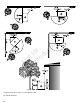
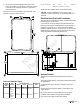
• Install the provided flexible fuel line (B) between the
generator fuel inlet port (A) and the rigid piping to
prevent thermal expansion and contraction from causing
excessive stress on the piping material.
• A union (C) or a flanged connection must be provided
downstream to permit removal.
• A manometer test port (D) should be installed for
vapor fuels. Use the port to install a manometer and
check if the engine receives the correct fuel pressure
for operation. A digital manometer (P/N 19495) or an
analogmanometeris available at your service center for
vapor fuels only. When the initial test runs are completed,
the manometer is removed and the port is plugged.
• For vapor fuels only: Where the formation of hydrates or
ice is known to occur, piping should be protected against
freezing. The termination of hard piping must include
a sediment trap (E) where condensate is not likely to
freeze.
• A minimum of one accessible, approved manual shutoff
valve (F) shall be installed in the fuel supply line within 6
ft (180 cm) of the generator.
• You must install a manual fuel shut-off valve in the interior
of the building.
• Where local conditions include earthquake, tornado,
unstable ground, or flood hazards, special consideration
shall be given to increase strength and flexibility of piping
supports and connections.
• Piping must be of the correct size to maintain the
required supply pressures and volume flow under
varying generator load conditions with all gas appliances
connected to the fuel system turned on andoperating.
• Use a pipe sealant or joint compound approved for
use with NG/LP on all threaded fittings to reduce the
possibility of leakage.
NOTICE Keep thread sealant out of the gas piping to
prevent component part damage.
• Installed piping must be properly purged and leak tested,
in accordance with applicable codes andstandards.
(A) Generator Fuel Inlet
(B)Flexible Fuel Line
(C)Union Fitting
(D)Manometer Test Port
(E)Sediment Trap
(F)Manual Shut-off Valve
Fuel Consumption
Estimated fuel supply requirements at half and full load for
natural gas and LP vapor fuels are shown below.
LP Vapor (Propane)
20 kW 17 kW
Cu Ft/Hr 135 118
Gal/Hr (liquid) 3.75 3.28
Full Load
BTU/Hr 337500 295000
Cu Ft/Hr 109 99
Gal/Hr (liquid) 3.03 2.75
3/4 Load
BTU/Hr 272500 247500
Cu Ft/Hr 83 74
Gal/Hr (liquid) 2.31 2.06
1/2 Load
BTU/Hr 207500 185000
Cu Ft/Hr 56 54
Gal/Hr (liquid) 1.56 1.5
1/4 Load
BTU/Hr 140000 135000
Cu Ft/Hr 40 40
Gal/Hr (liquid) 1.11 1.11
Exercise
BTU/Hr 100000 100000
Natural Gas
Not for
Reproduction