
Installation manual


5
Installation
We sincerely appreciate your patronage and have made significant
effort to provide for a safe, streamlined and cost-effective
installation. Because each installation is unique, it is impossible
to know of and advise the trade of all conceivable procedures and
methods by which installation might be achieved. Neither could we
know of possible hazards and/or the results of each method
or procedure.
For these reasons, only current licensed electrical professionals
should attempt system installations. Installations must strictly
comply with all applicable codes, industry standards and
regulations.
Your equipment is supplied with this Installation Manual and a
separate Operator’s Manual. These are important documents and
should be retained by the owner after the installation has
been completed.
Every effort has been made to make sure that the information
in this manual is both accurate and current. However, the
manufacturer reserves the right to change, alter or otherwise
improve the system at any time without prior notice.
Owner Responsibilities
To help you make informed choices and communicate effectively
with your installation contractor(s), read and understand Owner
Orientation before contracting or starting your
equipment installation.
To arrange for proper installation, contact the store at which you
purchased your equipment, your dealer, or your utility
power provider.
The equipment warranty is VOID unless the system is installed by
licensed electrical professionals.
Owner Orientation
The illustrations provided are for typical circumstances and are
meant to familiarize you with the installation options available with
your system.
Local codes, appearance, and distances are the factors that must
be considered when planning an installation. As the distance from
the existing electrical service increases, compensation in wiring
materials must be allowed for. This is necessary to comply with
local codes and overcome electrical voltage drops.
These factors will have a direct effect on the overall price of your
equipment installation.
Your installer must check local codes AND obtain permits before
installing the system.
• Readandfollowtheinstructionsgiveninthismanual.
• Followaregularscheduleincaringforandusingyour
equipment, as specified in this manual.
Installing Dealer/Contractor Responsibilities
• ReadandobservetheImportantSafetyInstructions.
• Readandfollowtheinstructionsgiveninthismanual.
• Theinstallermayneedtoprovideappropriateratedcontactors
based on loads to be controlled.
• Checkfederal,stateandlocalcodesandauthorityhaving
jurisdiction, for questions on installation.
• Ensuregeneratorisnotoverloadedwithselectedloads.
If you need more information about the transfer switch, call
800-743-4115, between 8:00 AM and 5:00 PM CST.
Equipment Description
The transfer switch is designed to transfer selected loads found
in normal residential installations to standby power in the event
of a primary power outage. The load is connected either to utility
power (normal) or standby power (generator). The transfer switch
monitors utility and generator voltages and will automatically
connect loads to the appropriate source of power.
Only a licensed electrician should complete a standby installation.
Service conduit and conductors can be wired directly from the
watt-hour meter to the transfer switch. A separate service entrance
disconnect and associated wiring is not required when installed per
applicable federal, state and local codes, standards andregulations.
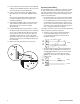
Major components of the transfer switch are three, 2-pole
circuit breakers (one for generator disconnect and two for
utility disconnect), two, 2 pole double throw transfer switches,
transfer switch control circuit board, fused utility terminals and
interconnecting wiring. All of these components are housed in a
NEMA3R enclosure that is suitable for both indoor and outdoor
installations.
The transfer switch is solenoid-operated from utility or generator
inputs and contain suitable mechanical and electrical interlock
switches to eliminate the possibility of connecting the utility service
to the generator output. It has ratings capable of switching full
utility power into the residence. In addition, a manual override lever
is provided for the transfer function.
The control board has active circuits sensing utility and generator
voltages. It creates a signal for generator start-up, switch transfer
and retransfer when utility is restored. The control board also
contains red and green LEDs indicating the power source available
and two relay operated contacts that provide supervisory control of
external loads.
Delivery Inspection
After opening the carton, carefully inspect the transfer
switch components for any damage that may have occurred
duringshipment.
If loss or damage is noted at time of delivery, have the person(s)
making delivery note all damage on the freight bill and affix their
signature under the consignor’s memo of loss or damage. If loss
or damage is noted after delivery, contact the carrier for claim
procedures. Missing or damaged parts are not warranted.
Shipment contents:
• Automatictransferswitch
• Installationandoperator’smanuals
• Currenttransformers(2)
To be supplied by installer:
• Connectingwireandconduit
• Variousspecialtytools/equipment
NOT
for
REPRODUCTION