OPERATOR’S MANUAL Signature Professional Series Snowthrowers 1524 Models 1738 Models Mfg. No. 1695303 1695304 Mfg. No. 1695309 1695310 1695358 1695359 Description P1524E, Snowthrower P1524EX, Snowthrower (CE) 1628 Models Mfg. No. 1695305 1695306 Description P1738E, Snowthrower P1738EX, Snowthrower (CE) P1738E, Snowthrower P1738EX, Snowthrower (CE) Description P1628E, Snowthrower P1628EX, Snowthrower (CE) 1732 Models Mfg. No.
Table of Contents CONTENTS: Regular Maintenance Maintenance Schedule ..................................20 Checking Tire Pressure .................................20 Auger Gear Case Lubrication ........................20 Lubrication .....................................................21 Check / Lubricate Free-Hand Linkage ...........22 Lubricate Auger Shaft Assembly ...................22 Safety Rules & Information General............................................................2 Training ..............
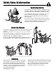
Safety Rules & Information Operating Safety Congratulations on purchasing a superior-quality piece of lawn and garden equipment. Our products are designed and manufactured to meet or exceed all industry standards for safety. Power equipment is only as safe as the operator. If it is misused, or not properly maintained, it can be dangerous! Remember, you are responsible for your safety and that of those around you. Use common sense, and think through what you are doing.
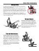
Safety Rules & Information Moving Parts This equipment has many moving parts that can injure you or someone else. However, if you are standing in the operator’s position, and follow all the rules in this book, the unit is safe to operate. The auger and impeller have spinning parts that can amputate hands and feet. Do not allow anyone near the equipment while it is running! DO NOT clear the discharge chute by hand.
Safety Rules & Information This machine is capable to amputating hands and feet and throwing objects. Read these safety rules and follow them closely. Failure to obey these rules could result in loss of control of unit, severe personal injury or death to you, or bystanders, or damage to property or equipment. The triangle in text signifies important cautions or warnings which must be followed. TRAINING OPERATION 1.
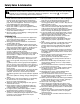
Safety Rules & Information 8. Always follow the engine manual instructions for storage preparations before storing the unit for both short and long term periods. 9. Always follow the engine manual instructions for proper start-up procedures when returning the unit to service. 10. Maintain or replace safety and instruction labels as necessary. 11. Keep nuts and bolts tight and keep equipment in good condition. 12. Never tamper with safety devices.
6
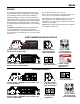
Decals DECALS This unit has been designed and manufactured to provide you with the safety and reliability you would expect from an industry leader in outdoor power equipment. The safety decals below are on your unit.
Decals and Safety Icons ALL MODEL DECALS Part No. 1734789 Deflector Decal - down Part No. 1734786 Shift Decal - left Part No. 1734787 Shift Decal - right SAFETY ICONS Part No. 1734788 Deflector Decal - up WARNING: DISMEMBERMENT. This machine can amputate limbs. Keep bystanders and children away when engine is running. WARNING: READ OPERATOR’S MANUAL. DANGER: DISMEMBERMENT. Read and understand the Operator’s Manual before using this machine. The auger can amputate limbs.
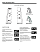
Identification Numbers SA M North American / CE Models PL E Part No. xxxxxxx SA M xxxxxxxxxxxxxxx Serial No. xxxxxxxxxx xxx PL 20xx E xxxxxxxxxxxxxxxxxxxxxxx xxxxxxxxxxxxxxxxxxxxxxx xxxxxxxxxxxxxxxxxxxxxxx xxxxxxxxxxxxxxxxxxxxxxx CE Models (Only) dB kg: xxx kW: x.xx xxxx max PRODUCT REFERENCE DATA Model Description Name/Number Identification Numbers When contacting your authorized dealer for replacement parts, service, or information you MUST have these numbers.
Features, Controls & Operation Please take a moment and familiarize yourself with the name, location, and function of these controls so that you will better understand the safety and operating instructions provided in this manual. 1,2.. Manual Rotator Model Electric Rotator Model CONTROL LOCATIONS The information below briefly describes the function of individual controls. Starting, stopping, and driving require the combined use of several controls applied in specific sequences.
Features & Controls Auger Control Fuel Engages the auger/impeller when depressed. Releasing the control stops the auger/impeller. Fuel tank filler cap (see illustration). Note: The fuel shut off valve is located under the fuel tank or on the front of the engine. Close the valve when the snowthrower is not in use. Open the valve before starting. Chute Direction Control Models with Electric Chute Rotator: Depressing the chute rotator switch rotates the chute left or right.
Operation GENERAL OPERATION WARNING This unit is a “two-stage” snowthrower. CHECKS BEFORE EACH START-UP The first stage is the auger, which feeds the snow back into the impeller housing. The second stage is the impeller, which throws the snow out the discharge chute. If bodily contact is made with the auger or impeller when they are rotating, severe personal injury will occur. 1. Make sure all safety guards are in place and all nuts, bolts and clips are secure. 2.
Operation STARTING CONTROLS G. Choke Knob - The choke knob (G) adjusts the air/fuel mixture, and is used to help start a cold engine by providing a richer mixture. Once the engine is warm and running smoothly, the choke knob should be set to the off position to provide a normal air/fuel mix. See Figure 1 for the following instructions. Electric Start A.
Operation STARTING THE ENGINE CAUTION WARNING This engine was shipped from Briggs & Stratton without oil. Before you start the engine, make sure you add oil according to the instructions in the Engine Owner’s Manual. If you start the engine without oil, it will be damaged beyond repair and will not be covered under warranty. Rapid retraction of starter cord (kickback) will pull hand and arm toward engine faster than you can let go. Broken bones, fractures, bruises or sprains could result.
Operation 4. Turn the fuel shut-off valve (B, Figure 2), if equipped, to the ON position. 5. Push in the safety key (C). 6. Turn the choke control knob (D) to the choke position. C A B NOTE: Do not use the choke to start a warm engine. 7. Push the primer button (E) two times. NOTE: Do not use the primer to start a warm engine. 8. Rewind Start: Firmly hold the starter cord handle (F). Pull the starter cord slowly until resistance is felt, then pull rapidly.
Operation OPERATING THE SNOWTHROWER ENGINE SPEED 1. Rotate the discharge chute to the desired direction. Always run the snowthrower at full throttle. 2. Set the speed selector to the desired forward speed. 3. Fully press and hold the auger engage control (C, Figure 4) on the right-hand grip to begin auger rotation. Releasing the auger engage control will disengage the auger — unless the Free-Hand™ Control has been activated (See step 5 below).
Operation DEFLECTOR The distance of the discharged snow is mainly controlled by the position of the deflector. (Engine speed also affects distance of discharge.) The more the deflector is tilted UP, the farther snow will be thrown. Models with Chute Deflector Knob See Figure 5. 1. Loosen the deflector knob, tilt the deflector UP or DOWN. 2. Retighten the knob when desired angle has been chosen. Models with Remote Deflector Control See Figure 6. 1.
Operation FULL TRACTION EASY TURN™ TRACTION Easy Turn™ Lever Engaged Easy Turn™ Lever Released Right Wheel Freewheels, Left Wheel Drives Both Wheels Drive Figure 8. Easy Turn Control A B EASY TURN™ FREEWHEELING AND TRACTION DRIVE LOCK While Clearing Snow: For easy turning when using the snowthrower, squeeze the Easy Turn™ lever (Figure 8). Engaging the Easy Turn™ lever releases the right traction wheel but allows the left wheel to continue driving (Figure 8).
Storage AFTER EACH USE STORAGE Normal use of the snowthrower may result in a build-up of packed snow in and around the starter cord housing and around engine controls. Heat from the engine will usually prevent the snow from freezing solid while the unit is running, but after the engine is shut down, some snow may continue melting from engine heat, and later freeze around some moving parts as the unit cools. WARNING Never store the unit (with fuel) in an enclosed, poorly ventilated structure.
Regular Maintenance MAINTENANCE SCHEDULE Maintenance Required Frequency Notes Check auger gear case lubrication.** 25 Hours Benalene 900 Grease Lubricate snowthrower. 10 Hours 10W Oil and Grease Check tire pressure. Monthly 20 psi (1,37 bar) Change engine oil.*✛ 50 Hours / Yearly See Engine Manual Yearly See Engine Manual 4-6 Hours N/A Yearly Lithium Grease Check / lubricate free-hand linkage. 10 Hours 10W Oil Lubricate auger shaft.
Regular Maintenance LUBRICATION A IMPORTANT NOTE It is very important that grease fittings on the auger shaft are lubricated regularly. If auger rusts to shaft, damage to worm gear may occur if shear pins do not break. To prevent wheels rusting to axles, it is also necessary to remove the wheels and grease the axles regularly. Figure 13. Drive Lubrication A. Hex Shaft Remove wheels and grease axles once each year. Apply medium weight (10W) oil to points shown (See Figures 12-15).
Regular Maintenance CHECK / LUBRICATE FREE-HAND LINKAGE A Check the function of the Free-Hand controls: the controls should function as described in the CONTROLS section. It is critical for the safe operation of the unit that the controls disengage when released. Lubricate as shown in Figures 16-17. IMPORTANT NOTE If the controls do not function properly, lubricate them. If lubrication does not rectify the problem, see your dealer.
Troubleshooting, Adjustments & Service TROUBLESHOOTING WARNING This section provides troubleshooting and service instructions. Locate the problem and check the possible cause/remedy in the order listed. Before performing any adjustment or service to snowthrower, stop the engine and wait for moving parts to stop. Remove the key. To prevent accidental starting, disconnect the spark plug wire and fasten away from the plug. Also, refer to the Engine Owner’s Manual for additional information.
Troubleshooting Problem Auger rotates, but snow is notthrown far enough. Possible Cause Remedy Chute deflector too low. Adjust deflector as necessary. Engine speed too slow. Set speed to full throttle. Ground speed too fast. Use slower speed selector setting. Snowthrower discharge chute clogged. STOP engine and REMOVE the key DISCONNECT the spark plug wire. Clear auger using clean-out tool. See warning in SAFETY RULES. Auger belt loose or worn. Check auger drive belt adjustment Poor traction.
Adjustments SPEED SELECTOR ADJUSTMENT B 1. Loosen the two nuts (C, Figure 19). C 2. Place the shift lever in 5th gear. A 3. Push the lower rod into the housing and tighten the two nuts (C). Do not lift up or down on rods while tightening. Make sure the shoulders of the carriage bolts (B) are in the slots. C B 4. Always check traction drive tension and auger drive tension after adjusting speed selector. AUGER DRIVE TENSION WARNING Figure 19. Speed Selector Linkage A. Shift Rod B. Carriage Bolts C.
Adjustments TRACTION DRIVE TENSION Initial Adjustment 1. Lift the bellcrank arm (C, Figure 21) up as far as it will go. 2. While holding the bell crank arm (C) up, adjust the cable until all the slack is removed. A 3. Back the adjustment screw (E) out 7-8 turns. Tighten nut (D). D 4. Start engine and check that the system disengages when the control is released.
Adjustments MANUAL DISCHARGE CHUTE CONTROL LINKAGE ADJUSTMENT F A E Pinion Gear Adjustment If the discharge chute is difficult to operate, first lubricate the pinion gear (A, Figure 22) and ring gear (F). If it is still difficult to operate, adjust as follows: NOTE: If the discharge chute will not stay in position, adjust the pinion gear (A) closer to the ring gear (F). B 1. Loosen the nut (G, Figure 22) which holds the pinion gear bracket in the slotted hole. D 2.
Adjustments & Service EASY TURN™ CABLE ADJUSTMENT If the Easy Turn™ cable has stretched, the gears will not disengage when the control lever is activated. Adjust the cable using the following procedure. 1. Turn the engine off and disconnect the spark plug wire. B 2. Loosen the jam nut (B, Figure 25). 3. Turn the adjustment nut (A) to lengthen or shorten the cable.
Adjustments & Service BELT REPLACEMENT A 1. Turn off the engine, remove the spark plug wire, and wait for all moving parts to stop. Rotate the spout full right. Loosen the two screws (B, Figure 27) securing the belt cover. 2. Tilt the cover forward and work it off the snowthrower. 3. Move the belt guides (B, Figure 28) by loosening the two capscrews (A). 4. Remove the auger drive belt as follows: a.
Service 6. Reverse the procedure to install the belts. Be sure there are no twists and the belts are properly seated in the grooves. Adjust the belt stops so there is 1/8” (3mm) clearance between belt and stop. The pattern for both belts is shown in Figure 30. Slide the right axle left fully before tightening the set collar (E, Figure 29). 7. Check the traction drive tension and auger drive tension. Follow the procedures under AUGER/TRACTION DRIVE TENSION. 8.
Specifications NOTE: Specifications are correct at time of printing and are subject to change without notice. * The gross power rating for individual gas engine models is labeled in accordance with SAE (Society of Automotive Engineers) code J1940 (Small Engine Power & Torque Rating Procedure), and rating performance has been obtained and corrected in accordance with SAE J1995 (Revision 2002-05). Torque values are derived at 3060 RPM; horsepower values are derived at 3600 RPM.
Parts & Accessories For applicable manuals currently available for your model, contact our Customer Publications Department at +1-877-249-6647. Have the information listed in the box below available when phoning in your request. Technical manuals can be downloaded from: REPLACEMENT PARTS Replacement parts are available from your authorized dealer. Always use genuine Simplicity / Snapper Service Parts. www.simplicitymfg.com MAINTENANCE ITEMS www.snapper.
MANUFACTURING, INC. 500 N Spring Street / PO Box 997 Port Washington, WI 53074-0997 www.SimplicityMfg.com PRODUCTS, INC. 535 Macon Street McDonough, GA 30253 www.Snapper.com © Copyright 2007, BRIGGS & STRATTON All Rights Reserved. Printed in USA.