MODEL 37641401 - 02 PECO OWNERS MANUAL FOR A SCAG UNIT P# Q0119 CONGRATULATIONS AND THANK YOU FOR BUYING THIS PECO LAWN VACUUM. Your new PeCo Vac has been engineered and manufactured to PeCo's high standards for safety, quality and dependability and ease of operations.
WARRANTY PeCo Limited Warranty for New Products A. WHAT IS WARRANTED? PeCo extends the following warranties to the original purchaser of each new PeCo consumer product subject to the following limitations. 1. PRODUCT WARRANTY.
SAFETY Outdoor Power Equipment Institute Recommendations WARNING TO PURCHASERS OF INTERNAL COMBUSTION ENGINE EQUIPPED MACHINERY OR DEVICES IN THE STATE OF CALIFORNIA: The equipment which you have purchased does not have a spark arrester muffler. If this equipment is to be used on any forest covered and brush covered land or grass covered unimproved land in the state of California, the law requires that a spark arrester muffler be installed and be in effective working order.
ASSEMBLY MOWER FRAME STEP 1: Remove plate on rear of mower as shown. Redrill top two holes for a 3/8"-16 hex bolt to mount Mount Frame onto mower frame. HOLES TO MOUNT TO TRACTOR FIG. 1-1 DESIGNATION OF HOLES ON THE MOUNT PLATE STEP 2: Use (2) 3/8"-16 x 2" (#K1208) and (2) 3/8"-16 flange nuts (#K1215) to secure Mount Plate (A) to mower frame. Use (2) 1" spacers (#S0138) between Mount Plate (A) and mower frame. Place (1) Bracket (B) on each side of Mount Plate (A).
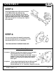
ASSEMBLY STEP 3: Slide Engine Mount Arm (B) into the receiver on the Mount Plate (A) and fasten by dropping in ball pin (#J0248). Place Engine/ Blower Assembly onto Engine Mount Arm (B) and fasten with (4) 5/16"-18 x 1 1/2 hex bolts (#K1157) and (4) 5/16"-18 flange nuts. Tighten nuts and bolts. A B STEP 4: A The ears of the Cone (A) should fit underneath the two threaded bosses on the Blower Face (B). Secure with (2) 5/16"-18 x 2" cone bolts.
PARTS LIST REF. NO. 1 2 3 4 5 6 PART NO.
EXPLODED VIEW MODEL 37641402 17 10 9 16 22 18 19 22 21 11 14 20 12 25 24 8 26 7 1 6 5 2 4 MODEL 37641401 - 04 3 PeCo 7
ASSEMBLY STEP 5: Attach Wheel (A) to Caster Fork (B) by using (1) axle (B4236), (1) flat washer (K0017), (2) spacers (S3315), (1) push nut (K0199), and (1) cotter pin (K0085). Next attach assembled Caster (C) to Hitch (D) by using (2) 1" washers (K0064) and (1) cotter pin (K0089). Attach Hitch Assembly (D) to Main Frame (E) by using (4) 3/8"-16 x 2 1/2" hex bolts and (4) 3/8"-16 flange nuts. Slide arm to open jaws on Hitch (D) and attach to the Mount Plate (F) and lock jaws. Place (2) 7 cu. ft.
ASSEMBLY STEP 7: Attach Boot Retainer to Boot with 3/8" x 1" carriage bolts and 3/8" flange nuts as shown. TIGHTEN NUTS AND BOLTS! STEP 8: Lift mower deflector and hang Boot Plate as shown. STEP 9: Place Clamp over each end of Lower Hose. Attach one end of hose over the Blower Cone. Tighten Clamp. Slide free end of hose over Boot and tighten clamps.
MAINTENANCE Your Lawn Vac was designed and built to provide years of service with only minor care. Certain tasks however must be performed to keep it in good operating condition and to avoid costly repairs. This section describes and provides procedures for the necessary care of the Lawn Vac. SCHEDULED CARE CARE REQUIRED Before Each Use Check engine oil. Check all hose connections. After Each Use Clean Collector Box, hoses and engine of all grass and dirt.
TROUBLE SHOOTING Diagnostic Procedures Trouble shooting procedures are provided in the chart below. To use these procedures, first locate the problem description that best describes the trouble that you have encountered. Check the possible causes one at a time in the list. Correct any problems that are found and operate the vacuum collector again to verify that you have eliminated the problem. DO NOT attempt any major repairs without first contacting your dealer.
P.O. Box 1197 Arden, North Carolina 28704 1-800-438-5823 or (828) 684-1234 fax-(828) 684-0858 email: peco@ioa.