
Product Manual


7
Delivery Inspection
After opening the carton, carefully inspect the transfer
switch components for any damage that may have occurred
duringshipment.
If loss or damage is noted at time of delivery, have the person(s)
making delivery note all damage on the freight bill and affix his
signature under the consignor’s memo of loss or damage. If loss
or damage is noted after delivery, contact the carrier for claim
procedures. Missing or damaged parts are not warranted.
Shipment contents:
• Automatictransferswitch
• Installationandoperator’smanuals
• Currenttransformers(2)
Optional components:
• 50Ampmodule
• Lowvoltagemodule(singleordualmodels)
• Symphony™IIpowermonitor
To be supplied by installer:
• Connectingwireandconduit
• Variousspecialtytools/equipment
Testing the Automatic Transfer Switch
Turn the utility service disconnect circuit breaker feeding the
transfer switch contactor to the OFF position. The system’s
automatic sequence described below will initiate. To return to utility
power, turn the utility service disconnect circuit breaker to
the ON position.
Utility Fail
The generator senses when utility voltage is below 70percent of
nominal. Engine start sequence is initiated after
6second time delay.
Engine Warm-Up
Time delay to allow for engine warm-up before transfer. Use jumper
on transfer switch control board to select delay of 20seconds
or 50 seconds.
Transfer
Transfer from utility to generator supply occurs after voltage is
above set levels. The transfer switch control board LED lights will
change from green (utility) to red (generator) and the Symphony II
status light will change blink status from Blink Blink_Pause_Blink
Blink to Blink_Pause_Blink. Minimum engine run time is
5 minutes after transfer.
Load Management
Five minutes after transfer to generator power, the remote modules
energize connected load(s) if generator power is available, starting
with the highest priority (1) through the lowest priority (8). There is
a 10 second delay between each sequential activation.
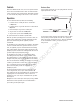
The P1 through P8 LED’s (A) on the Symphony II control board will
illuminate to show loads being added.
Loads connected to remote modules set to priorities 9 and 10
remain off for the duration of a utility power outage.
Utility Pickup
Voltage pickup level is 80 percent of nominal voltage.
Retransfer
Retransfer from generator to utility power is approximately 10
seconds after utility voltage supply is above pickup level and
minimum run time is completed. All remote module(s) will remain
OFF for five minutes after the power transfer.
Engine Cool Down
Engine will run for 60 seconds after retransfer.
WARNING Shock Hazard. Equipment contains high voltage
that could cause electrocution resulting in death or
serious injury.
• Testing must only be performed by qualified personnel.
• Do not operate this equipment imprudently, carelessly or neglect
its maintenance.
NOT
for
REPRODUCTION