Installation, Start-Up and Operator’s Manual Manual de Instalación, Arranque y Operario Manuel d'Installation, Démarrage et Utilisation Questions? Help is just a moment away! Preguntas? La ayuda es justa un momento lejos! Vous avez des questions? Vous n'avez pas besoin d'aller loin pour trouver de l'aide! Call: Home Standby Generator Helpline Llamada: Línea Directa de Reserva de Hogar Appelez: Ligne Directe de Secours À la Maison - 1-800-743-4115 M-F 8-5 CT Web: www.briggspowerproducts.
Briggs & Stratton Power Products Home Standby Generator Installation, Start-Up and Operator’s Manual TABLE OF CONTENTS TABLE OF CONTENTS . . . . . . . . . . . . . . . . . . . . . . . . . . . 2 IMPORTANT SAFETY INSTRUCTIONS . . . . . . . . . . . . 3-4 SAVE THESE INSTRUCTIONS . . . . . . . . . . . . . . . . . . . . . . 5 INTRODUCTION . . . . . . . . . . . . . . . . . . . . . . . . . . . . . . . 5 CUSTOMER RESPONSIBILITIES . . . . . . . . . . . . . . . . . . . . 5 INSTALLER RESPONSIBILITIES . . . . . . . . .
Briggs & Stratton Power Products Home Standby Generator Installation, Start-Up and Operator’s Manual SAVE THESE INSTRUCTIONS IMPORTANT SAFETY INSTRUCTIONS DANGER Storage batteries give off explosive hydrogen gas during recharging. Slightest spark will ignite hydrogen and cause explosion. Battery electrolyte fluid contains acid and is extremely caustic. Contact with battery contents will cause severe chemical burns. A battery presents a risk of electrical shock and high short circuit current.
Briggs & Stratton Power Products Home Standby Generator Installation, Start-Up and Operator’s Manual CAUTION WARNING Excessively high operating speeds increase risk of injury and damage to generator. Excessively low speeds impose a heavy load. Generator produces powerful voltage. Failure to properly ground generator can result in electrocution. Failure to isolate generator from power utility can result in death or injury to electric utility workers due to backfeed of electrical energy.
Briggs & Stratton Power Products Home Standby Generator Installation, Start-Up and Operator’s Manual SAVE THESE INSTRUCTIONS CUSTOMER RESPONSIBILITIES • Read and follow the instructions given in this manual, especially the section regarding selecting essential circuits. • Follow a regular schedule in maintaining, caring for and using your Home Standby Generator, as specified in this manual.
Briggs & Stratton Power Products Home Standby Generator Installation, Start-Up and Operator’s Manual KNOW YOUR HOME STANDBY GENERATOR Read this operator’s manual and safety rules before operating your generator. Compare the illustrations with your generator to familiarize yourself with the locations of various controls and adjustments. Save this manual for future reference.
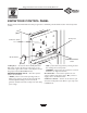
Briggs & Stratton Power Products Home Standby Generator Installation, Start-Up and Operator’s Manual KNOW YOUR CONTROL PANEL Compare this Control Panel illustration with your generator to familiarize yourself with the location of these important controls: 15 Amp Fuse Set Exercise Switch cise Exer Set mp 15 A e s u F l anua ff/M O / Auto er reak uit B Circ Circuit Breaker AUTO/OFF/MANUAL Switch 15 Amp Fuse — Protects the Home Standby Generator DC control circuits.
Briggs & Stratton Power Products Home Standby Generator Installation, Start-Up and Operator’s Manual OWNER ORIENTATION WARNING Propane and Natural Gas are extremely flammable and explosive. Fire or explosion can cause severe burns or death. This section provides the Home Standby Generator owner with the information necessary to achieve the most satisfactory and cost effective installation possible.
Briggs & Stratton Power Products Home Standby Generator Installation, Start-Up and Operator’s Manual Shipment Contents General Location Guidelines WARNING The Home Standby Generator is supplied with: • Home Standby Generator w/disconnect box • Pre-attached mounting pad • One 24” flexible hook-up hose • Installation, start-up and operator’s manual • Installation checklist • Remote diagnostic LED plate • Oil drain tray • Touch-up paint • One spare 15A fuse • LP conversion kit • Roof hardware bag Running
Briggs & Stratton Power Products Home Standby Generator Installation, Start-Up and Operator’s Manual Essential Circuits Figure 2 — Wattage Reference Guide Consult with owner to clearly identify the circuits in building that are "essential".
Briggs & Stratton Power Products Home Standby Generator Installation, Start-Up and Operator’s Manual Fuel Inlet Dimensions This rating is applicable to installations served by a reliable normal utility source.This rating is only applicable to variable loads with an average load factor of 80% of the standby rating.The standby rating is only applicable for optional standby power where the generator set serves as the backup to the normal utility source.
Briggs & Stratton Power Products Home Standby Generator Installation, Start-Up and Operator’s Manual THE GASEOUS FUEL SYSTEM • Piping must be of the correct size to maintain the required supply pressures and volume flow under varying generator load conditions with all gas appliances connected to the fuel system turned on and operating. WARNING • Use an approved pipe sealant or joint compound on all threaded fittings to reduce the possibility of leakage.
Briggs & Stratton Power Products Home Standby Generator Installation, Start-Up and Operator’s Manual • Where the formation of hydrates or ice is known to occur, piping should be protected against freezing.The termination of hard piping should include a sediment trap where condensate is not likely to freeze. When the initial test runs are completed, the manometer is removed and the port is plugged. A typical final fuel connection assembly is shown in Figure 6.
Briggs & Stratton Power Products Home Standby Generator Installation, Start-Up and Operator’s Manual Fuel Pipe Sizing Listed values compensate for a nominal amount of restriction from bends, fittings, etc. If an unusual number of fittings, bends, or other restrictions are used, please refer to federal and local codes. Figures 8 and 9 provide the maximum capacity of pipe in cubic feet of gas per hour for gas pressures of 0.5 psi or less and a pressure drop of 0.3 in. water column.
Briggs & Stratton Power Products Home Standby Generator Installation, Start-Up and Operator’s Manual Fuel Comparison Chart Fuel Comparison Chart Physical Properties Normal Atmospheric State Boiling Point (in °F): Initial End Heating Value: BTU per gallon (Net LHV*) BTU per Gallon (Gross**) Cubic Feet (Gas) Density*** Weight† Octane Number: Research Motor Propane Gas Natural Gas Gas -44 -44 -259 -259 83,340 91,547 2,516 36.39 4.24 63,310 110+ 97 110+ 1,000 57.75 2.
Briggs & Stratton Power Products Home Standby Generator Installation, Start-Up and Operator’s Manual WIRE CONNECTIONS Remote Diagnostic LED Plate The light on the remote LED plate is referred to as the Diagnostic LED.The LED will stay lit indicating the generator is in ready mode and will turn on and off in a series of blinks if certain faults are detected in the Home Standby Generator.A mounting plate is supplied so that it can be installed at a convenient indoor location.
Briggs & Stratton Power Products Home Standby Generator Installation, Start-Up and Operator’s Manual Battery Connection NOTE: With the battery installed and utility power available to the Automatic Transfer Switch, the battery receives a trickle charge whenever the engine is not running.This process may take up to 72 hours to fully charge a battery from 5 Volts.The trickle charge cannot be used to recharge a battery that is completely discharged. 5.
Briggs & Stratton Power Products Home Standby Generator Installation, Start-Up and Operator’s Manual FUEL SYSTEM SELECTION 9. The engine of your Home Standby Generator is factory calibrated to run on natural gas (NG). It may also be operated on liquid propane (LP). To configure the fuel system for LP use: 1. LP fuel inlet pressure must be between 11 and 14 inches water column. 2. Set AUTO/OFF/MANUAL switch to OFF. 3. Pull service disconnect from disconnect box. 4. Remove 15 Amp fuse. 5.
Briggs & Stratton Power Products Home Standby Generator Installation, Start-Up and Operator’s Manual SETTING EXERCISE TIMER For example, if you press the “Set Exercise” switch on Sunday morning at 10:00 AM, the unit will run an exercise cycle the following Sunday at 10:00 AM (+/- 1 hour). The Home Standby Generator is equipped with an exercise timer that will start and exercise the generator once every seven days.
Briggs & Stratton Power Products Home Standby Generator Installation, Start-Up and Operator’s Manual SPECIFICATIONS 2. With generator output supplying load, turn ON service disconnect or main distribution panel circuit breaker that supplies utility power to automatic transfer switch. 3. Automatic transfer switch will transfer loads back to utility power after five minute minimum run time and utility is restored. 4.
Briggs & Stratton Power Products Home Standby Generator Installation, Start-Up and Operator’s Manual between each series.The number of blinks in the series indicates the detected fault, as listed on the mounting plate and as follows: Number of LED Flashes Fault Description 2 Low oil pressure 4 Engine failed to start 5 Low frequency 6 Engine overspeed Engine Fail To Start This fault is indicated by four blinks.This feature prevents the generator from damage by continually attempting to start.
Briggs & Stratton Power Products Home Standby Generator Installation, Start-Up and Operator’s Manual GENERATOR MAINTENANCE 4. Slide oil drain tube up into clamp on generator. Changing Oil Filter 1. Place oil drain tray over tubing and slide it under oil filter (Figure 13). The generator warranty does not cover items that have been subjected to operator abuse or neglect.To receive full value from the warranty, the operator must maintain the engine as instructed in the engine operator’s manual.
Briggs & Stratton Power Products Home Standby Generator Installation, Start-Up and Operator’s Manual To Clean the Generator When Calling the Factory • Use a damp cloth to wipe exterior surfaces clean. You must have the following information at hand if it is necessary to contact a local service center regarding service or repair of this unit: CAUTION Improper treatment of generator can damage it and shorten its life. • DO NOT expose generator to excessive moisture, dust, dirt, or corrosive vapors.
Briggs & Stratton Power Products Home Standby Generator Installation, Start-Up and Operator’s Manual TROUBLESHOOTING Problem Engine is running, but no AC output is available. Engine runs good at no-load but "bogs down" when loads are connected. Cause Correction 1. Circuit breaker open or defective. 1. Reset or replace circuit breaker. 2. Fault in generator. 2. Contact local service facility. 3. Poor wiring connections or defective transfer switch. 3. Check and repair. 1.
Briggs & Stratton Power Products Home Standby Generator Installation, Start-Up and Operator’s Manual NOTES 25
Briggs & Stratton Power Products Home Standby Generator Installation, Start-Up and Operator’s Manual SCHEMATIC 26
Briggs & Stratton Power Products Home Standby Generator Installation, Start-Up and Operator’s Manual WIRING DIAGRAM 27
Briggs & Stratton Power Products Home Standby Generator Installation, Start-Up and Operator’s Manual EXPLODED VIEW - MAIN UNIT 28
Briggs & Stratton Power Products Home Standby Generator Installation, Start-Up and Operator’s Manual PARTS LIST - MAIN UNIT Item Part # 1 B191860GS 2 194568GS 3 193536GS 4 191793GS 5 NSP 6 194728GS 7 * 8 96796GS 9 193012GS 10 75246GS 11 187365HGS 12 194990GS 13 193605GS 14 194569GS 15 692236 16 83512GS 17 193064GS 18 698941 19 194159GS 20 195008GS 21 194209GS 22 192940GS 23 * 24 192853GS 25 186071GS 26 74908GS 34 192906GS 35 194992GS 48 15253621GS 49 01916 900 § Description WELDMENT, Cradle ASSY, Duct, Ai
Briggs & Stratton Power Products Home Standby Generator Installation, Start-Up and Operator’s Manual EXPLODED VIEW - ENCLOSURE 30
Briggs & Stratton Power Products Home Standby Generator Installation, Start-Up and Operator’s Manual PARTS LIST - ENCLOSURE Item Part # 1 NSP 2 NSP 3 195224GS 4 195226GS 5 H191853GS 6 194751GS 7 195228GS 8 77816GS 9 194793GS 10 194993GS 11 194991GS 12 B191860GS 13 * 14 190849GS 16 193506GS 17 * 18 195642GS 48 15253621GS Description PAD, Drilled, ELS BASE, Plate PANEL, Right side PANEL, Front PANEL, Left Side COVER, Oil Filter Drain KIT, Baffle, Air In-take w/Seals DECAL, Caution Hot Muffler ASSY, Unit Cov
Briggs & Stratton Power Products Home Standby Generator Installation, Start-Up and Operator’s Manual EXPLODED VIEW - CONTROL PANEL 32
Briggs & Stratton Power Products Home Standby Generator Installation, Start-Up and Operator’s Manual PARTS LIST - CONTROL PANEL Item Part # 1 195229GS 2 195227GS 3 195225GS 4 195004GS 5 195003GS 6 190818EGS 7 87799GS 8 * 9 * 10 * 11 193423GS 12 195006GS 13 192455GS 14 186173GS 15 186582GS 16 195007GS 17 * 18 195009GS 19 * 20 * 21 * 22 193171GS 23 691656 24 194659GS 25 194251GS 26 188573AGS 27 194250GS 28 193347GS 29 188443GS 30 193291GS 31 186151GS 32 186148GS 33 186150GS 34 195005GS 35 193537CGS 36 192449
Briggs & Stratton Power Products Home Standby Generator Installation, Start-Up and Operator’s Manual EXPLODED VIEW AND PARTS LIST - ALTERNATOR Item Part # 1 186059GS 2 195430GS 3 193091AGS 4 193336GS 5 86308KGS 6 66386GS 7 66849GS 8 22694GS 9 81917GS 10 193472GS 11 192906GS 12 74908GS 13 65791GS Description ADAPTER, Mounting, Alternator ROTOR (Includes Item 13) STATOR RBC, (with O-Ring p/n 189197GS) HHCS, M6 - 1.0 x 140 SEMS ASSY, Holder, Brush TAPTITE, M5 - 0.
BRIGGS & STRATTON POWER PRODUCTS GROUP, LLC EQUIPMENT OWNER WARRANTY POLICY Effective September 1, 2005 replaces all undated Warranties and all Warranties dated before September 1, 2005 LIMITED WARRANTY Briggs & Stratton Power Products Group, LLC will repair or replace, free of charge, any part(s) of the equipment that is defective in material or workmanship or both. Transportation charges on product submitted for repair or replacement under this warranty must be borne by purchaser.
Generador Doméstico de Briggs & Stratton Power Products Manual de Instalación, Arranque y Operario TABLA DE CONTENIDO Conexión a Tierra del Sistema. . . . . . . . . . . . . . . . . . . . . . . 50 Interconexiones del Circuito de Control . . . . . . . . . . . . . . 50 Placa de LED Remoto . . . . . . . . . . . . . . . . . . . . . . . . . . . . . 50 ANTES DEL ARRANQUE INICIAL. . . . . . . . . . . . . . . . . . . . . . . 50 Aceite de Motor. . . . . . . . . . . . . . . . . . . . . . . . . . . . . . . . . .
Generador Doméstico de Briggs & Stratton Power Products Manual de Instalación, Arranque y Operario CONSERVE ESTAS INSTRUCCIONES INSTRUCCIONES IMPORTANTES DE SEGURIDAD PELIGRO Las baterías almacenadas producen hidrógeno explosivo mientras estén siendo recargadas. Una pequeña chispa puede encender el hidrógeno y causar una explosión. El fluido de electrolito de la batería contiene ácido y es extremadamente cáustico. El contacto con el fluido de la batería puede causar quemaduras químicas severas.
Generador Doméstico de Briggs & Stratton Power Products Manual de Instalación, Arranque y Operario PRECAUCIÓN ADVERTENCIA Las velocidades de operación en exceso, aumentan los riesgos de heridas y daños al generador. Las velocidades bajan en exceso, imponen una carga muy pesada. Los generadores producen un voltaje muy poderoso. Si no hace tierra apropiadamente con un generador, puede hacer que ocurra un electrocutamiento.
Generador Doméstico de Briggs & Stratton Power Products Manual de Instalación, Arranque y Operario CONSERVE ESTAS INSTRUCCIONES RESPONSABILIDADES DEL INSTALADOR Este manual contiene instrucciones importantes que se deben seguir durante la instalación y el mantenimiento del generador y de la batería. • Lea y observe las reglas de seguridad que se encuentran en este manual. • Lea y siga las instrucciones que se encuentran en este manual.
Generador Doméstico de Briggs & Stratton Power Products Manual de Instalación, Arranque y Operario CONOZCA SU GENERADOR DE RESERVA Lea este manual del operario y las reglas de seguridad antes de operar su generador. Compare las ilustraciones con su Generador para familiarizarse con las ubicaciones de los diferentes controles y ajustes. Conserve este manual para referencias futuras.
Generador Doméstico de Briggs & Stratton Power Products Manual de Instalación, Arranque y Operario CONOZCA EL PANEL DE CONTROL Compare esta ilustración del panel de control con su generador para familiarizarse con la ubicación de estos controles importantes: Interruptor de Configuración de Práctica Fusible de 15 Amperios cise Exer Set mp 15 A e s u F l anua ff/M O / Auto er reak uit B Circ Disyuntor Interruptor AUTO/OFF/MANUAL • Fusible de 15 Amperios - Protege los circuitos de control de c.c.
Generador Doméstico de Briggs & Stratton Power Products Manual de Instalación, Arranque y Operario ORIENTACIÓN PARA EL PROPIETARIO ADVERTENCIA El Gas Natural y el Propano son extremadamente inflamables y explosivos. El fuego o una explosión pueden causar quemaduras severas e inclusive la muerte. En esta sección se brinda al propietario del generador de reserva la información necesaria para lograr la instalación más rentable y satisfactoria posible.
Generador Doméstico de Briggs & Stratton Power Products Manual de Instalación, Arranque y Operario Pautas Generales para la Ubicación del Generador Contenido de la Caja El • • • • • • • • • • • ADVERTENCIA generador de reserva incluye lo siguiente: Generador de reserva de reserva con cuadro de desconexión Placa de montaje fijada previamente Un tubo de enganche flexible de 24" Manual de instalación, de puesta en marcha y del operario Lista de verificación de la instalación Placa de LED de diagnóstico rem
Generador Doméstico de Briggs & Stratton Power Products Manual de Instalación, Arranque y Operario Circuitos Fundamentales Figura 15 — Guía de Referencia de Potencia Consulte con el propietario para identificar claramente los circuitos del edificio que sean "esenciales". Dispositivo Es importante comprender cuáles son los circuitos que el propietario desea incluir como "circuitos esenciales".
Generador Doméstico de Briggs & Stratton Power Products Manual de Instalación, Arranque y Operario Dimensiones de la Entrada de Combustible Estos valores nominales son aplicables a instalaciones alimentadas por una fuente de energía eléctrica normal fiable. Este valor nominal sólo es aplicable a cargas variables con un factor de carga medio del 80% del valor nominal de reserva.
Generador Doméstico de Briggs & Stratton Power Products Manual de Instalación, Arranque y Operario SISTEMA DE COMBUSTIBLE GASEOSO ADVERTENCIA El Gas Natural y el Propano son extremadamente inflamables y explosivos. El fuego o una explosión pueden causar quemaduras severas e inclusive la muerte. • La cañería debe tener las dimensiones correctas que permitan mantener las presiones de suministro requeridas y el volumen de caudal en condiciones variables.
Generador Doméstico de Briggs & Stratton Power Products Manual de Instalación, Arranque y Operario Una vez que las operaciones de prueba iniciales están completas, se retira el manómetro y se tapa la abertura. En la Figura 19 se muestra un conjunto típico de conexión de combustible final. ADVERTENCIA El Gas Natural y el Propano son extremadamente inflamables y explosivos. El fuego o una explosión pueden causar quemaduras severas e inclusive la muerte.
Generador Doméstico de Briggs & Stratton Power Products Manual de Instalación, Arranque y Operario Dimensiones de la Cañería de Combustible En los valores indicados se ha tenido en cuenta una cantidad normal de restricciones debidas a curvas, accesorios, etc. Si se utiliza un número inusual de accesorios, curvas u otras restricciones, consulte los reglamentos nacionales y locales. Las Figuras 21 y 22 indican la capacidad máxima de la cañería en pies cúbicos de gas por hora para presiones de gas de 0.
Generador Doméstico de Briggs & Stratton Power Products Manual de Instalación, Arranque y Operario Cuadro de Comparación de Combustibles Cuadro de Comparación de Combustibles Propiedades físicas Estado normal a presión atmosférica Punto de ebullición (en °F): Propano Gas Inicial Final Poder calorífico BTU por galón (LHV Neto*) BTU por galón (bruto**) Pies cúbicos (gas) Densidad*** Peso† Número de octanos: De investigación De motor * Gas natural Gas -44 -44 -259 -259 83 340 91 547 2516 36.39 4.
Generador Doméstico de Briggs & Stratton Power Products Manual de Instalación, Arranque y Operario CONEXIONES DE CABLES Placa de LED Remoto El indicador luminoso de la placa de LED remoto se denomina LED de diagnóstico. El LED permanecerá encendido para indicar que el generador está preparado y parpadeará cuando se detecten ciertos fallos en el generador de reserva. Se suministra una placa de montaje que se puede instalar en un punto interior adecuado.
Generador Doméstico de Briggs & Stratton Power Products Manual de Instalación, Arranque y Operario NOTA: Con la batería instalada y tensión de la red aplicada al interruptor automático de transferencia, la batería recibe una carga lenta siempre que el motor no está funcionando. Mediante este proceso, la carga de una batería con una tensión de 5 V puede tardar hasta 72 horas. La carga lenta no se puede utilizar para cargar una batería que se haya descargado por completo. 5.
Generador Doméstico de Briggs & Stratton Power Products Manual de Instalación, Arranque y Operario SELECCIÓN DEL SISTEMA DE COMBUSTIBLE El motor del generador de reserva viene calibrado de fábrica para funcionar a gas natural (NG).También puede funcionar con propano líquido (PL). Para configurar el sistema de combustible para uso de PL: 1. Sin embargo, la presión de entrada del combustible PL debe estar entre las 11 y las 14 pulgadas en columna de agua. 7.
Generador Doméstico de Briggs & Stratton Power Products Manual de Instalación, Arranque y Operario Sensor de excitación de tensión de la compañía proveedora de electricidad 3. Presión y mantenga presionado el interruptor "Set Exercise" (preparar prueba) durante dos segundos. Este sensor vigila la tensión de alimentación de la red.
Generador Doméstico de Briggs & Stratton Power Products Manual de Instalación, Arranque y Operario ESPECIFICACIONES 3. El interruptor automático de transferencia transferirá de nuevo las cargas a la red después de un tiempo de funcionamiento de cinco minutos como mínimo, restableciéndose la alimentación desde la red. 4. El generador seguirá funcionando durante aproximadamente un minuto más para que se enfríe el motor y luego se parará. Potencia Nominal Máxima . . . . . . . . . . . . . . . . . . . . .
Generador Doméstico de Briggs & Stratton Power Products Manual de Instalación, Arranque y Operario Descripción de la Falla El Motor no Arranca 2 Baja presión de aceite 4 El motor no arranca 5 Baja frecuencia 6 Sobrevelocidad del motor Esta falla se indica mediante cuatro parpadeos. Esta función evita que el generador sufra daños al intentar arrancar continuamente, como por ejemplo que no haya suministro de combustible.
Generador Doméstico de Briggs & Stratton Power Products Manual de Instalación, Arranque y Operario MANTENIMIENTO DEL GENERADOR 4. Cambio del Filtro de Aceite La garantía del generador no cubre artículos que hayan sido sometidos al abuso o negligencia por parte del operador. Para recibir el valor total de la garantía, el operador debe dar mantenimiento al sistema de acuerdo con las indicaciones del manual del operario del motor. 1.
Generador Doméstico de Briggs & Stratton Power Products Manual de Instalación, Arranque y Operario Para Limpiar el Generador Si Llama a la Fábrica • En caso de que sea necesario consultar al Servicio técnico de Briggs & Stratton respecto a servicios o reparaciones de esta unidad, usted debe tener disponible la siguiente información: Utilice un trapo húmedo para limpiar las superficies exteriores. PRECAUCIÓN El tratamiento inadecuado del generador puede dañarlo y acortar su vida productiva.
Generador Doméstico de Briggs & Stratton Power Products Manual de Instalación, Arranque y Operario REPARACION DE AVERIAS Problema El motor está funcionando pero no hay salida de c.a. disponible. El motor funciona cuando no tiene carga pero "se atasca" cuando se conectan las cargas. El motor no arranca o arranca pero funciona con dificultad. El motor se apaga durante la operación. Pérdida de potencia en los circuitos fundamentales. Causa Corrección 1.
POLÍTICA DE GARANTÍA PARA EL PROPIETARIO DE EQUIPOS BRIGGS & STRATTON POWER PRODUCTS GROUP, LLC Fecha de entrada en vigor: 1 de Septiembre de 2005. Sustituye a todas las garantías sin fecha y a las de fecha anterior al 1 de Septiembre de 2005 GARANTÍA LIMITADA Briggs & Stratton Power Products Group, LLC reparará o sustituirá sin cargo alguno cualquier componente del equipo que presente defectos de materiales y/o mano de obra.
Génératrice d’état d’Attente Briggs & Stratton Manuel d'Installation, Démarrage et Utilisation TABLE DES MATIÈRES Système de Branchement C.A. de la Génératrice. . . . . . . . 74 Mise à la Masse du Système . . . . . . . . . . . . . . . . . . . . . . . . . 74 Interconnexions du Circuit de Commande. . . . . . . . . . . . . 74 Plaque DEL à distance . . . . . . . . . . . . . . . . . . . . . . . . . . . . . 74 AVANT LE DÉMARRAGE INITIAL . . . . . . . . . . . . . . . . . . . . . . . 74 Huile à Moteur . . . . . .
Génératrice d’état d’Attente Briggs & Stratton Manuel d'Installation, Démarrage et Utilisation VEUILLEZ CONSERVER CES INSTRUCTIONS DIRECTIVES DE SÉCURITÉ IMPORTANTES DANGER Les batteries d'accumulateur produisent du gaz hydrogène explosif lorsqu'elles se rechargent. La plus petite étincelle enflammera l'hydrogène et provoquera une explosion. Le liquide d'électrolyte de l'accumulateur contient de l'acide et est extrêmement caustique.
Génératrice d’état d’Attente Briggs & Stratton Manuel d'Installation, Démarrage et Utilisation AVERTISSEMENT ATTENTION Les vitesses de fonctionnement excessivement élevées augmentent les risques de blessure ou risquent d'endommager le générateur. Les vitesses extrêmement lentes entraînent une charge importante. Le générateur produit une tension élevée. NE PAS relier le générateur à la terre risque de provoquer des électrocutions.
Génératrice d’état d’Attente Briggs & Stratton Manuel d'Installation, Démarrage et Utilisation CONSERVEZ CES INSTRUCTIONS RESPONSABILITÉS DE L'INSTALLATEUR Ce manuel contient d'importantes directives qu'il faut suivre lors de l'installation et de la maintenance de la génératrice et de la batterie. INTRODUCTION Merci d'avoir acheté une génératrice Briggs & Stratton.
Génératrice d’état d’Attente Briggs & Stratton Manuel d'Installation, Démarrage et Utilisation FAMILIARISEZ-VOUS AVEC VOTRE GÉNÉRATRICE D’ÉTAT D’ATTENTE Lire ce manuel de l'utilisation et les régles de sécurité avant de faire marcher votre générateur. Comparez les illustrations avec votre générateur pour vous familiariser avec l'emplacement des diverses commandes et réglages. Gardez ce manuel pour le consulter plus tard.
Génératrice d’état d’Attente Briggs & Stratton Manuel d'Installation, Démarrage et Utilisation FAMILIARISEZ-VOUS AVEC LE TABLEAU DE COMMANDE Comparez la présente illustration au tableau de commande de votre génératrice afin de vous familiariser avec l'emplacement des importantes commandes suivantes: Interrupteur de Réglage du Cycle d'Exercice Fusible de 15 Ampères cise Exer Set ual Man Off/ / o t Au er reak uit B c r i C Disjoncteur Interrupteur AUTO/OFF/MANUAL Disjoncteur - Protège le système des s
Génératrice d’état d’Attente Briggs & Stratton Manuel d'Installation, Démarrage et Utilisation CONSEILS AU PROPRIÉTAIRE AVERTISSEMENT La présente section présente au propriétaire du génératrice d’état d’attente les renseignements dont il aura besoin pour que l'installation du génératrice d’état d’attente soit la plus satisfaisante et économique possible. Le gaz propane et le gaz naturel sont extrêmement inflammables et explosifs.
Génératrice d’état d’Attente Briggs & Stratton Manuel d'Installation, Démarrage et Utilisation compte des vents dominants et des courants d'air au moment de choisir l'endroit où vous installerez la génératrice.
Génératrice d’état d’Attente Briggs & Stratton Manuel d'Installation, Démarrage et Utilisation Circuits Essentiels Figure 28 — Guide de Référence de Puissance Consultez le propriétaire de l'immeuble pour en identifier clairement les circuits "essentiels". Appareil Il est important de bien comprendre quels circuits le propriétaire souhaite inclure parmi les " circuits essentiels ".
Génératrice d’état d’Attente Briggs & Stratton Manuel d'Installation, Démarrage et Utilisation Dimensions de l'Orifice d'Admission du Combustible Cette puissance nominale s'applique aux installations desservies par un service électrique normalement fiable. Cette puissance ne s'applique qu'aux charges variables avec facteur de charge moyen de 80 % de la puissance de réserve.
Génératrice d’état d’Attente Briggs & Stratton Manuel d'Installation, Démarrage et Utilisation LE SYSTÈME DE COMBUSTIBLE GAZEUX AVERTISSEMENT Le gaz propane et le gaz naturel sont extrêmement inflammables et explosifs. Le feu ou l'explosion risque de provoquer des blessures graves, pouvant être fatales. • La tuyauterie doit être de la bonne dimension afin de maintenir les pressions d'alimentation ainsi que le débit volumétrique nécessaires sous diverses conditions.
Génératrice d’état d’Attente Briggs & Stratton Manuel d'Installation, Démarrage et Utilisation Lorsque la série initiale d'essais est complétée, le manomètre est enlevé et la sortie bouchée. La Figure 32 présente un assemblage typique de raccord de combustible. AVERTISSEMENT Le gaz propane et le gaz naturel sont extrêmement inflammables et explosifs. Le feu ou l'explosion risque de provoquer des blessures graves, pouvant être fatales.
Génératrice d’état d’Attente Briggs & Stratton Manuel d'Installation, Démarrage et Utilisation Grosseur du Tuyau de Combustible Les valeurs indiquées compensent pour une quantité nominale de restrictions causées par les lyres de dilatation, les joints, etc. Si la tuyauterie comporte une quantité anormalement élevée de joints, de lyres de dilatation ou d'autres restrictions, reportez-vous aux codes fédéraux et locaux.
Génératrice d’état d’Attente Briggs & Stratton Manuel d'Installation, Démarrage et Utilisation Charte de Comparaison des Combustibles Charte de Comparaison des Combustibles Propriétés physiques Propane État atmosphérique normal Point d’ébullition (en °F) : Initial Final Valeur calorifique : Btu par gallon (LHV net*) Btu par gallon (Brut**) Pieds cubes (Gaz) Densité*** Poids† Indice d’octane : Recherche Moteur * Gaz naturel Gaz Gaz -44 -44 -259 -259 83 340 91 547 2 516 36,39 4,24 63 310 110+ 97
Génératrice d’état d’Attente Briggs & Stratton Manuel d'Installation, Démarrage et Utilisation À l'aide d'un fil de cuivre torsadé d'au moins 300 V et 16 AWG, fourni par l'installateur, raccordez les terminaux du circuit de commande du boîtier de débranchement au commutateur de transfert. RACCORDS DE FILS Couples de Serrage Recommandés Serrez au couple tous les raccords/attaches selon les valeurs recommandées indiquées à la Figure 36. Convenable pour le fil de cuivre de 60°/75°C classement.
Génératrice d’état d’Attente Briggs & Stratton Manuel d'Installation, Démarrage et Utilisation REMARQUE : Alors que la batterie est installée, que tous les câbles reliant le commutateur de transfert et le groupe électrogène sont branchés, que l'électricité de service est fournie au commutateur de transfert automatique et que l'unité est en mode AUTO, la batterie reçoit une charge à faible débit si le moteur n'est pas en marche.
Génératrice d’état d’Attente Briggs & Stratton Manuel d'Installation, Démarrage et Utilisation SÉLECTION DU SYSTÈME DE COMBUSTIBLE 7. Écoutez s'il y a des bruits ou vibrations inhabituels et soyez attentif à tout signe de fonctionnement anormal.Vérifiez s'il y a des fuites d'huile pendant que la génératrice fonctionne. Le moteur de votre génératrice d’état d’attente est calibré en usine pour utiliser le gaz naturel (GN). Il peut également fonctionner avec du gaz de pétrole liquéfié (GPL).
Génératrice d’état d’Attente Briggs & Stratton Manuel d'Installation, Démarrage et Utilisation Minuterie de Refroidissement du Moteur • Par exemple, si vous appuyez sur l'interrupteur de réglage du cycle d'exercice le dimanche à 10 h, l'unité exécutera un cycle d'exercice le dimanche suivant à 10 h. Lorsque la charge est transférée à nouveau à la source d'alimentation de service, la minuterie de refroidissement du moteur s'active. • Environ une minute s'écoule avant l'arrêt de la génératrice.
Génératrice d’état d’Attente Briggs & Stratton Manuel d'Installation, Démarrage et Utilisation CARACTÉRISTIQUES 2. Alors que la génératrice alimente ses charges, mettez SOUS tension l'interrupteur de débranchement ou le disjoncteur principal du panneau de distribution qui alimente le commutateur de transfert automatique. 3. L'interrupteur de transfert automatique transférera les charges à l'alimentation de service après 5 minutes de fonctionnement minimum et du rétablissement de l'électricité. 4.
Génératrice d’état d’Attente Briggs & Stratton Manuel d'Installation, Démarrage et Utilisation Le Moteur Ne Démarre Pas Nombre de Clignotements du Voyant Lorsque ce problème survient, le voyant émet une série de quatre clignotements. Cette caractéristique protège la génératrice contre les tentatives répétées de démarrage, comme par exemple un manque de combustible.
Génératrice d’état d’Attente Briggs & Stratton Manuel d'Installation, Démarrage et Utilisation ENTRETIEN DU GÉNÉRATEUR Changement du filtre à huile La garantie de la génératrice ne couvre pas les éléments soumis à l'abus ou à la négligence de l'opérateur. Pour obtenir la pleine application de la garantie, il faut que l'opérateur maintienne le système conformément aux instructions du manuel d'utilisation du moteur. 1.
Génératrice d’état d’Attente Briggs & Stratton Manuel d'Installation, Démarrage et Utilisation Pour Nettoyer le Générateur Communications avec le Fabricant • Si vous devez communiquer avec le service technique de la société Briggs & Stratton pour l'entretien ou la réparation de cette unité, ayez en main les renseignements suivants: 1. Notez le numéro de modèle ainsi que le numéro de série de l'unité, lesquels sont indiqués sur le décalque apposé sur l'unité.
Génératrice d’état d’Attente Briggs & Stratton Manuel d'Installation, Démarrage et Utilisation DÉPANNAGE Problème Le moteur fonctionne, mais il n'y a aucune sortie de C.A. Le moteur tourne bien sans charge mais connaît des ratés lorsque les charges sont branchées. Le moteur ne démarre pas, ou il démarre et a des ratés. Le moteur s'arrête lorsqu'il est en marche. Perte de puissance sur les circuits essentiels. Cause Solution 1. Disjoncteur ouvert ou défectueux. 1.
Génératrice d’état d’Attente Briggs & Stratton Manuel d'Installation, Démarrage et Utilisation REMARQUES 83
GARANTIE DU PROPRIÉTAIRE D'UN PRODUIT BRIGGS & STRATTON POWER PRODUCTS GROUP, LLC Prise d’effet au 1 er Septembre 2005, annule et remplace toutes les garanties précédentes et les garanties antérieures au 1 er Septembre 2005 GARANTIE LIMITÉE Briggs & Stratton Power Products Group, LLC réparera ou remplacera, sans frais, toutes pièces d'équipement défectueuses comportant un vice de matériau ou un défaut de fabrication ou les deux.