GE Home Generator Systems Home Generator System N O fo T R r EP R O D U C TI O N Installation and Start-Up Manual 1
Thank you for purchasing this quality-built GE home generator. We’re pleased that you’ve placed your confidence in the GE brand. When operated and maintained according to the instructions in the operator’s manual, your home generator will provide many years of dependable service. This manual contains safety information to make you aware of the hazards and risks associated with standby generators and how to avoid them.
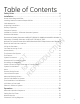
Table of Contents Safety Rules . . . . . . . . . . . . . . . . . . . . . . . . . . . . . . . . . . . . . . . . . . . . . . . . . . . . 4 Installation . . . . . . . . . . . . . . . . . . . . . . . . . . . . . . . . . . . . . . . . . . . . . . . . . . . . . 7 N O fo T R r EP R O D U C TI O N Home Owner Responsibilities . . . . . . . . . . . . . . . . . . . . . . . . . . . . . . . . . . . . . . . . . . . . . . . . . . . . . 7 Installing Dealer/Contractor Responsibilities . . . . . . . . . . . . . . . .
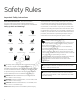
Safety Rules Important Safety Instructions Explosion Electrical Shock Fire Hot Surface Explosive Pressure Chemical Burn O Auto Start Rotating Parts fo T R r EP R O D U Toxic Fumes Read Manual N Lift Hazard The safety alert symbol indicates a potential personal injury hazard. A signal word (DANGER, WARNING, or CAUTION) is used with the alert symbol to designate a degree or level of hazard seriousness. A safety symbol may be used to represent the type of hazard.
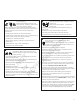
WARNING Generator produces hazardous voltage. Failure to properly ground generator could result in electrocution. Failure to isolate generator from utility power could result in death or serious injury to electric utility workers due to backfeed of electrical energy. DO NOT touch bare wires or bare receptacles. DO NOT use generator with electrical cords which are worn, frayed, bare or otherwise damaged.
• • • • • N O • WARNING Starter and other rotating parts could entangle hands, hair, clothing, or accessories resulting in serious injury. • NEVER operate generator without protective housings, covers, or guards in place. • DO NOT wear loose clothing, jewelry or anything that could be caught in the starter or other rotating parts. • Tie up long hair and remove jewelry. • Before servicing, remove 15 Amp fuse from control panel and disconnect Negative (NEG or -) battery cable.
Installation • Emergency generator systems are intended to automatically supply illumination, power, or both, to designated areas and equipment in the event of failure of the normal supply. Emergency systems may also provide power for such functions as ventilation where essential to maintain life, where current interruption of the normal supply would produce serious life safety or health hazards.
Cold Weather Kit If operating the generator below 30°F (-1°C), it is HIGHLY RECOMMENDED that a Model 6231 Cold Weather Kit (includes oil warmers and battery warmer) be installed. These items are available at your local servicing dealer. For cold weather areas (below 0°F (-18°C)) it is also recommended that a BCI, Size 75, wet lead-acid battery be used of 630 CCA minimum. 30°F (-1°C) If you need more information on this matter, please call (888) 575-8226, between 8:00 AM and 5:00 PM CT.
Installation Checklist - GE Home Generator Systems Proper installation of the home generator requires the completion of the following tasks: Carbon Monoxide (CO) Detector/ Smoke Detector Carbon Monoxide (CO) detector(s) installed and in working order. Smoke detector(s) installed and in working order. Operation Cold weather kit is installed in temperatures below 40°F (5°C). See Cold Weather Kit. Placement Required permits have been obtained. Correct battery type is installed and fully charged.
N C TI O N O fo T R r EP R O D U Intentionally Left Blank 10
Generator Placement Before installing the generator, consult with the homeowner and convey the following requirements, which must be satisfied before the installation is complete. There are two equally important safety concerns in regards to carbon monoxide poisoning and fire. There are also several general location guidelines that must all be met before the installation is considered complete. WARNING Running engine gives off carbon monoxide, an odorless, colorless, poison gas.
Placement of Standby Generator to REDUCE THE RISK OF CARBON MONOXIDE POISONING • Ensure exhaust gas is kept away from: B windows C doors fo T R r EP R O D U All fossil fuel burning equipment, such as standby generators, contains carbon monoxide (CO) gas in the engine exhaust. CO gas is odorless, colorless and tasteless and is unlikely to be noticed until a person is overcome.
• Direct the standby generator exhaust away from or parallel to the building or structure. DO NOT direct the generator exhaust towards a potentially occupied building, structure, windows, doors, ventilation intakes, soffit vents, crawl spaces, open garage doors or other openings where exhaust gas could accumulate and enter inside or be drawn into a potentially occupied building or structure.
Placement of Standby Generator to REDUCE THE RISK OF FIRE The National Fire Protection Association (NFPA) standard NFPA 37 establishes criteria for minimizing the hazard of fire during the installation and operation of stationary combustion engines. NFPA 37 limits the spacing of an enclosed generator from openings in walls, structures and combustible materials outside the enclosure. • Exhaust outlet side of weatherproof enclosure must have at least 5 ft. (1.
NOTICE The figures below show the minimum installation distances allowed to structures and items in the legend. Generator Installations A A D A D 18 in (45.7 cm) min 5 ft (1.5 m) min 5 ft (1.5 m) min Exhaust Direction Standby B Standby 5 ft (1.5 m) 5 ft (1.5 m) Exhaust Direction D C TI O N B 18 in (45.7 cm) min fo T R r EP R O D U 18 in (45.7 cm) min D A D A D 5 ft (1.5 m) min Standby Standby N O Exhaust Direction 5 ft (1.5 m) A 5 ft (1.
Other General Location Guidelines • Place the standby generator in a prepared location that is flat and has provisions for water drainage. • Install the standby generator where leaves, grass, snow, etc will not obstruct air inlet and outlet openings. If prevailing winds will cause blowing or drifting, you may need to construct a windbreak to protect the unit.
Electrical and Fuel Inlet Locations The 3/4 inch N.P.T. fuel inlet connector A and electrical inlet location B is shown below. The home generator is supplied with a base that, unless mandated by local code, does not require a concrete slab. B N O fo T R r EP R O D U C TI O N A ½ inch knock-out is provided for the electrical inlet. This inlet may be enlarged or supplemented to accommodate a maximum conduit size of 1 ½ inches.
Lifting the Generator The generator weighs more than 500 pounds (227 kg). Proper tools, equipment and qualified personnel should be used in all phases of handling and moving the generator. WARNING Hazardous Voltage - Contact with power lines could cause electric shock or burn, resulting in death or serious injury. Lifting Hazard / Heavy Object - Could result in serious injury. • If lifting or hoisting equipment is used, DO NOT contact any power lines. • DO NOT lift or move generator without assistance.
Access Panels The generator is equipped with an enclosure that has several access panels, as shown. The access panels and the components located behind them are listed below: AA - Roof (Control Panel, air filter, oil dipstick, and circuit breaker) Each generator is shipped with a set of identical keys. These keys fit in the lock on the front removable panel. The roof must be unlocked in order for it to open.
To open roof: To remove rear panel: 1. Insert key into lock A of front panel. Gently push down on roof above the lock to aid in turning the key. Turn key one quarter turn clockwise. 1. Ensure the roof is in the open position. 2. Lift roof to the open position. 3. Lift panel to remove from unit. To remove front panel: 1. Remove the two bolts B that secure the panel to the unit. 2. Lift panel to remove from unit. 2. Remove the two bolts C that secure the panel to the unit. To secure rear panel: 1.
The Gaseous Fuel System TO THE INSTALLER: Consult with the generator owner(s) and convey any technical considerations that might affect their installation plans before applying these general guidelines. The following general rules apply to gaseous fuel system piping: B A F • A union C or flanged connection shall be provided downstream to permit removal of standby. • A manometer port should be provided D . A digital manometer, P/N 19495, is available at your Briggs & Stratton service center.
Fuel Factors Fuel Pressure • In engines set up to run on propane (LP), commercial grade HD5 propane with a minimum fuel energy of 2500 BTUs/ft3 with maximum propylene content of 5% and butane and heavier gas content of 2.5% and minimum propane content of 90% is required. Natural gas rating will depend on specific fuel but typical derates are between 10 to 20% off the LP gas rating.
Fuel Conversion The engine of your generator system is factory calibrated to run on natural gas (NG) or on liquefied petroleum (LP) vapor. To convert to either fuel, follow these steps: NOTICE Units are set to NG at the factory. 1. Insert key into lock of front panel. Gently push down on roof above the lock to aid in turning the key. Turn key one quarter turn clockwise. 6. Locate the fuel selector switch (A). A located on top of the fuel regulator B(B.
Fuel Consumption Estimated fuel supply requirements at half and full load for natural gas and LP vapor fuels are shown here. LP Vapor (Propane) 1/4 Load Exercise Cu Ft/Hr 135 118 109 Recommended Energy Content of Fuel: Gal/Hr (liquid) 3.75 3.28 3.03 Heating Value: BTU/Hr 337500 295000 272500 Cu Ft/Hr 109 99 90 Gal/Hr (liquid) 3.03 2.75 2.5 BTU/Hr 272500 247500 225000 Cu Ft/Hr 83 74 68 Gal/Hr (liquid) 2.31 2.06 1.
System Connectors Low Voltage connections to signal fault contacts, transfer switch communication and auxiliary 12VDC power are made via a field connection terminal block in control board area. Compare this illustration with your generator to familiarize yourself with the location of these connections. A UTILITY A UTILITY B ]] NEUTRAL GROUND ]] G LINE 1 F LINE 2 O N C TI O ]] ]] B ]] C D D – +LED and GND Connection — Not required for wireless monitor included with unit.
Generator AC Connection System NOTICE Neutral is not bonded to ground at generator. NOTICE Generator must be used with only an UL approved transfer switch that is compatible with the generator. 33 Neutral 22 Power Winding A single-phase, three-wire AC connection system is used in the home generator. The stator assembly consists of a pair of stationary windings with two leads brought out of each winding.
Power Connections from Generator to Transfer Switch Utility Circuit Connection “240V Utility” leads must be routed in conduit. The “240V Utility” leads deliver power to the generator’s circuit board, optional battery warmer and optional oil warmer. This power also charges the battery. When power on these leads is lost, the generator will start.
System Control Board The generator control board, located inside the generator, under the roof, is shown below. Brief descriptions of the controls used during installation are: A - Menu/Programming Navigation Buttons — See Menu section for details B - Mini USB Port — Authorized Dealer Service Use Only C - Generator Operation Control Buttons — •“AUTO” Normal operating position. Press and hold button to put unit into Automatic mode. If an utility power outage is sensed, the system will start the generator.
Menu The following chart shows the icons for the buttons that control the system control panel. MENU ENTER THE MENU (VIEW SETTINGS) PRESS TO CONFIRM SELECTION WHEN PROGRAMMING. ok ok ok ESCAPE (EXIT) RETURN TO LAST MENU ITEM RIGHT ARROW TOGGLE THROUGH MENU OPTIONS SETTING SYSTEM PARAMETERS LEFT ARROW TOGGLE THROUGH MENU OPTIONS SETTING SYSTEM PARAMETERS MANUAL MODE USED TO MANUALLY START THE GENERATOR. PRESS AND HOLD BUTTON TO START THE GENERATOR.
ko ok ko General Set Up Screen For general set up, press and hold the left arrow and right arrow for 3 seconds. Follow the prompts as outlined below. NOTE: Date and Time were set at the factory and stored in the control panel memory. The Exercise Cycle was also set at the factory. The default exercise cycle occurs on Tuesdays, at 2:00 P.M. Central Standard Time. To updated or change these settings, follow the steps below.
Control Panel Prompts Automatic Mode In Automatic Mode, the display screen will display via scrolling text: • GENERATOR READY - if the unit is in standby and utility power is present. • GENERATOR ON - if the unit is running and utility power is not present. • SERVICE CODE - if a system fault has been detected.
Advanced Settings Screen Advanced setting parameters are preset at the factory for a typical installation. To view Advanced Settings items and/or to ko ok change items, follow the instructions listed below. NOTICE Advanced settings are critical to the operation of the unit. Careful consideration should be taken when working ko ko ok in the Advanced Settings menu. Exercise caution when selecting and verifying parameters for the generator and region ok where the generator is being operated.
Service Code Detection System The generator may have to run for long periods of time with no operator present. For that reason, the system is equipped with sensors that automatically shut down the generator in the event of potentially damaging conditions, such as low oil pressure, high temperature, over speed, and other conditions. Refer to Service Code Detection System in the operator’s manual for more detailed information.
Initial Start-up (No Load) A A A 2. Connect an accurate frequency meter to line side of generator’s main circuit breaker. 3. Set generator’s main circuit breaker to ON (closed) position. 4. Install 15 Amp fuse in control board. 6. Listen for unusual noises, vibration or other indications of abnormal operation. Check for oil leaks while engine runs. 7. Let engine warm up for about 5 minutes to allow internal temperatures to stabilize. 8. Check generator output at load side of circuit breaker.
Electronic Governor System The engine electronic governor system allows for improved control and increased generator performance compared to mechanically governed systems. The result is smooth steady-state operation without the "hunting" common to many mechanical governors. The system also reduces speed variations under engine loading and unloading and significantly reduces frequency fluctuation experienced when the engine is under higher loads.
Operation Automatic Operation Sequence The generator’s control board constantly monitors utility voltage. Should utility voltage drop below a preset level, the control board will signal the engine to crank and start. When utility voltage is restored above a preset voltage level, the engine is signaled to shut down.
Antenna Installation The supplied antenna must be installed before the wireless monitor will operate. 1. Insert key into lock of front panel. Gently push down on roof above the lock to aid in turning the key. Turn key one quarter turn clockwise. 5. Route antenna wire (D) D from the top side of the roof, through the hole in the roof where the plug was removed. 2. Lift roof to the open position. 6. Replace flange nut on wire. Ensure the wire is routed through the washer end. 3.
Wireless Monitor The generator is supplied with a battery-powered, wireless monitor. The monitor communicates wirelessly with the generator control panel. The monitor may be placed in a suitable location in the home. The system has a line-of-sight range of about 200 feet, but this distance will decrease if the signal has to pass through walls or other objects. The wireless monitor communicates with the generator, every 10 minutes and will display the status via LED lights on the front of the monitor.
Wireless Monitor Operation A on back of monitor 1. Remove battery access cover (A) and install 2 AA batteries. (Observe correct battery generator ready polarity which is embossed in the bottom of the battery compartment). Replace battery access cover.
Standard Operation: Wireless Monitor Status LED’s • The wireless monitor receives data from the generator every 10 minutes and displays the generator status through 3 LED’s. NOTICE None of the conditions on the display unit can be cleared at the wireless monitor. All alerts must be cleared at the generator control panel. • Pressing the system update button will provide current generator status by flashing the status LED’s. When pressed, all 3 LEDs will flash until the generator status is received.
N C TI O fo T R r EP R O D U O N NOTES 41
N C TI O fo T R r EP R O D U O N NOTES 42
Schematic / Wiring Diagrams N O fo T R r EP R O D U C TI O N Schematic Diagram 43
N O fo T R r EP R O D U C TI O N Wiring Diagram 44 is a trademark of General Electric Company and is under license by Briggs & Stratton Power Products Group, LLC. Copyright © 2012. All rights reserved. No part of this material may be reproduced or transmitted in any form without the express written permission of Briggs & Stratton Power Products Group, LLC.