BL-PRO-MIX-88/1818/3232 Modular Matrix Switcher Operation manual Version:V1.01.
BL-PRO-MIX- 8*8/18*18/32*32 Contents 1. Introduction ................................................................................................................ 3 2. Product index ............................................................................................................. 4 3. Connection and operation .......................................................................................... 5 4. BRIGHTLINK PRO-MIX E88 Standard configuration ............................................
BL-PRO-MIX- 8*8/18*18/32*32 Safety reminder To protect the device and operating personnel from electrostatic discharge, you need to check and ensure that the device is properly grounded before the device is powered on. Please observe the following when you install, use, or maintain this equipment. Make sure the device is well grounded. POWER SUPPLY: Use single-phase three wire system AC 220V power supply, and ensure that the transmission system is well grounded.
BL-PRO-MIX- 8*8/18*18/32*32 To avoid damaging the device, please turn off power supply before plugging or unplugging the power cable. Any damage caused by plugging / pulling cables without first turning off the power supply is outside the scope of the warranty. Do not operate the device in extremely cold or extremely hot environments. When working, the device may become very hot. Make sure that the work environment is ventilated and cool, otherwise it may be damaged from overheating.
BL-PRO-MIX- 8*8/18*18/32*32 Reticle (RJ45) Optical fiber Wireless signal input BRIGHTLINK PRO-MIX series matrix supports the following outputs: 3G/HD/SD-SDI HDMI DVI VGA YPBPR CVBS Reticle (RJ45) Optical fiber Wireless signal output All inputs and outputs support random seamless switching. BRIGHTLINK PRO-MIX series matrix also supports audio signal input/output.
BL-PRO-MIX- 8*8/18*18/32*32 input interface. VGA, YPBPR, CVBS adopts the VGA input interface. Reticle signal adopts the standard RJ45 interface. There is a 120m transmission distance reticle and a 70m transmission distance reticle. Optical fiber signal adopts the single core LC fiber interface. 4. Supports HDMI1.3 protocol, supports DVI1.0 protocol, supports HDCP protocol. 5. Supports 640*480/60Hz---1920*1200/60Hz (VESA standard), 480i---1080p (HDTV standard) input.
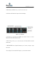
BL-PRO-MIX- 8*8/18*18/32*32 Test the switching functions via the IR remote control. If any of the displays fail to receive signal correctly, enter the menu of the display and adjust resolution from MIN to MAX until the signal is displayed as normal. A 24 Hz vertical refresh rate may work better than 60 Hz or higher. Application: The following diagram is an example application of the BL-PRO-MIX-1818 matrix switching system. 4.
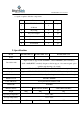
BL-PRO-MIX- 8*8/18*18/32*32 to repair or replace defective components. NO. Name Quantity BRIGHTLINK PRO-MIX Unit pcs 1 1 88 Matrix 2 Dryer 50g 1 pcs 3 AC power adapter 2 pcs 4 Certification 1 pcs 5 Warranty card 1 pcs 6 User manual 1 pcs 5.
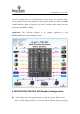
BL-PRO-MIX- 8*8/18*18/32*32 6. Description of operation and function 6.1 Description of front panel a. BL-PRO-MIX-88 front panel Figure 6.1.1 – front panel 1. INPUT: Input selection buttons 1~8. These allow you to select input ports. To select input 3, press button 3 on the INPUT row. To cancel the selection, press button 3 again. To select another input port, press any other input button. 2. OUTPUT: Output selection buttons 1~8. These allow you to select output ports.
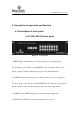
BL-PRO-MIX- 8*8/18*18/32*32 5. RECALL button: RECALL lets you recall / load a saved scene. 6. ALL button: ALL enables all outputs on the selected input. Figure 6.1.2 – back panel 1. LAN: This port is the link for the TCP/IP control method. Connect to an active Ethernet link with an RJ45 terminated cable. 2. RS232: This port allows you to connect the matrix to PC with an RS232 serial null modem cable. 3. INPUT/OUTPUT Area: Signal I/O interface ports. Connect your input / output devices here. 4.
BL-PRO-MIX- 8*8/18*18/32*32 b. BL-PRO-MIX-1818 front panel Figure 6.1.3 – front panel POWER: Power LED. ACTIVE: Data Transmitting Indicator. NETWORK: Network connected Status Indicator. Touchscreen LCD: Use the touchscreen LCD to control the in-out of the BRIGHTLINK PRO-MIX. Figure 6.1.
BL-PRO-MIX- 8*8/18*18/32*32 1. LAN: This port is the link for the TCP/IP control method. Connect to an active Ethernet link with an RJ45 terminated cable. 2. RS232: This port allows you to connect the matrix to PC with an RS232 serial null modem cable. 3. INPUT/OUTPUT Area: Signal I/O interface ports. Connect your input / output devices here. 4. Power Supply: Use the included DC adapter to power the matrix switcher. c. BL-PRO-MIX-3232 front panel Figure 6.1.5 – front panel POWER: Power LED.
BL-PRO-MIX- 8*8/18*18/32*32 Figure 6.1.6 – back panel 1. LAN: This port is the link for the TCP/IP control method. Connect to an active Ethernet link with an RJ45 terminated cable. 2. RS232: This port allows you to connect the matrix to PC with an RS232 serial null modem cable. 3. INPUT/OUTPUT Area: Signal I/O interface ports. Connect your input / output devices here. 4. Power Supply: Use the included DC adapter to power the matrix switcher. 6.2 Operating Instructions a.
BL-PRO-MIX- 8*8/18*18/32*32 Example 1: To switch the Channel 1 input to Channel 1, 3, 4 outputs, press button “1” on the Input row, then press buttons “1,3,4” in the Output row. Example 2: To switch the Channel 2 input to all Channel outputs, press button “2” in the Input row, then press button “ALL” in the Control area. You may view the status of inputs and outputs by pressing the “STATUS” button. The indicator LED will light up for each active channel.
BL-PRO-MIX- 8*8/18*18/32*32 Figure 6.2.1 – View screen Press “View” on the touchscreen LCD to check the current I/O status. You may save the scene from here by selecting a scene number from 00 to 11; see Figure 6.2.1. To recall a previously-saved scene, press the “Scene” button and select the scene number. You can review all the data, as shown in Figure 6.2.2.
BL-PRO-MIX- 8*8/18*18/32*32 Figure 6.2.2 – Scene Recall To configure input and output switching, press the “Switch” button. Example: Figure 6.2.3 shows the “Switch” screen with input Channel 02 selected. Once an input is selected, the list of output ports will now automatically pop-up, as shown in Figure 6.2.4. Choose the desired output port/s by ticking the appropriate checkbox. To cancel an output port selection, simply untick the checkbox.
BL-PRO-MIX- 8*8/18*18/32*32 Figure 6.2.3 – Input selection menu Figure 6.2.4 – Selection screen of output port Click the “Setup” button on the touch screen to configure the device’s network settings (IP address / Subnet mask / Gateway). See Figure 6.2.5.
BL-PRO-MIX- 8*8/18*18/32*32 Figure 6.2.5 – Device setup screen Remark: The touch screen operation method for the BL-PRO-MIX-3232 is identical to that of the BL-PRO-MIX-1818. Please refer to BL-PRO-MIX-1818’s operation method to use. 6.3 Using the Host PC software The BL-PRO-MIX matrix switcher can be controlled remotely by PC using either a RS232 COM Serial Port connection or TCP/IP LAN connection. To start the host software, copy “Client.exe” to your computer and then double-click to launch it.
BL-PRO-MIX- 8*8/18*18/32*32 Figure 6.3.1 a. Control Method 1: Serial Port RS232 control Step 1: Connect the computer’s RS232 port to the matrix’s RS232 port with a Straight (i.e. Direct / Crossover) RS232 cable. Step 2: Determine the COM port number of the matrix as it appears to the computer. To find this information on Windows, open up Device Manager and view the Ports (COM & LPT) list. Step 3: Click the “SET” tab in the matrix software application.
BL-PRO-MIX- 8*8/18*18/32*32 Step 4: In the “SET” panel on the left side of the screen, click the “Load” button. If the connection is successful, parameters of the matrix will now appear on the interface. See Figure 6.3.2. Figure 6.3.2 b. Control Method 2: LAN Port control Step 1: Connect the computer’s Ethernet LAN port to the matrix’s LAN port with an RJ45 Ethernet cable. Step 2: Click the “SET” tab in the matrix software application.
BL-PRO-MIX- 8*8/18*18/32*32 Step 3: In the “SET” panel on the left side of the screen, click “Save”. If the connection is successful, the status bar is displayed as green. Step 4: Click “Load” to load the matrix parameters, as seen in Figure 6.3.3. Please note: It is necessary to configure the PC’s IP address when we use LAN port control mode. See Figure 6.3.4. The factory address for the 192.168.0.80, must set the address to a 192.168.0.
BL-PRO-MIX- 8*8/18*18/32*32 Figure 6.3.4 6.4 PC operation: Changing input/output labels To change INPUT signal names, first click “SWITCH” to enter the switching interface. Now, select input No.1 and double click it. A dialog box as shown in Figure 6.4.1 pops up. Change the name of the No.1 input signal and then save it.
BL-PRO-MIX- 8*8/18*18/32*32 Figure 6.4.1 To change OUTPUT signal names, first click “SWITCH” to enter the switching interface. Now, select out No.1 and double click it. A dialog box as shown in Figure 6.4.2 pops up. Change the name of the No.1 output signal and then save it.
BL-PRO-MIX- 8*8/18*18/32*32 Figure 6.4.2 6.5 Switching operation of matrix Press “SWITCH” to enter the switching interface. Choose the input port first, then choose the needed output port on the pop-up interface (the selected port turns yellow). See Figure 6.5.1. Click the number again to cancel the output port, and the port turns grey. You can choose multiple ports at a time. After all selections have been made, press “OK” to activate the switching operation. Figure 6.5.
BL-PRO-MIX- 8*8/18*18/32*32 Figure 6.5.2 The No.1 input channel can be switched to No.1, 2, 3, 4, 5, 8 output channels by operating as demonstrated in Figure 6.5.1 and 6.5.2. 6.6 Save scene operation of matrix Press “SAVE/VIEW” to enter the Save/View interface. See Figure 6.6.1. Press “Previous” to check the current configuration of the matrix. To save a specific scene, for example Scene1, choose “Scene1” and then press “Load”. This will load and save the scene’s current I/O configuration.
BL-PRO-MIX- 8*8/18*18/32*32 Figure 6.6.1 6.7 Load scene operation of matrix Press “LOAD” to enter the Load Scene interface. See Figure 6.7.1. Choose “Scene1” and then press “Load” to load the scene saved in “Scene1”. To verify the scene has been loaded correctly, check the specific configuration of the loaded scene on the right side of the interface.
BL-PRO-MIX- 8*8/18*18/32*32 Figure 6.7.1 6.8 FAQ 1. Serial Port operation is out of order / cannot control the switching Possible causes: The serial port is damaged or not connected properly, the serial cables are not of the correct type, or the serial connection has not been initialized. Solution: Make sure the RS232 ports are connected using a crossover / null modem serial cable, and double-check the connection of the PC software serial port. See Section 6.3.
BL-PRO-MIX- 8*8/18*18/32*32 Accidental damage: Please send back to the manufacturer for repair. 7. Communication protocol and control instruction code Communication protocol: (Baud rate 115200, data bits 8, stop bit 1, no parity bit) Type Opera ting instruc tions Control instruction aXb.take. aX1-b.take. aXb1,b2,b3.take. a1Xb1.a2Xb2.a3 Xb3.take. Save[Y]. Recall[Y].
BL-PRO-MIX- 8*8/18*18/32*32 2. Input“1X1-5.take.” to switch No. 1 channel input to No. 1-5 channels output. 3. Input “1X3,4,5.take.” to switch No. 1 channel input to No. 3,4,5 channel output. 4. Input “4X3.5X4.6X5.take.” to switch No. 4,5,6 channel input to No. 3,4,5 channel output. 5. Save current scene: Save[Y]. Example: Input “Save7.” to save the current scene to No.7 storage unit. 6. Load the saved code: Recall[Y]. Example: Input “Recall7.” to load the scene saved in No.7 storage unit. 7.