
Installation Instructions

28 Elan 25 Uitgave D juli 2011
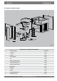
Hoofdstuk 10 Elektrische schema’
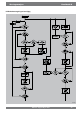
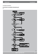
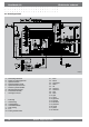
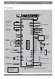
10.1 Bedradingsschema
E1993-E
A = Netvoeding 230V50Hz
B = Display en bedieningspaneel
C = Systeemventilator
D = Retourtemperatuurvoeler
E = Systeemtemperatuurvoeler
F = Interface systeemventilator
G = Besturingsunit ECS 907
H = Insteekvoet koelrelais
I = 20-Polige connector
I = koelvraag
II = warmtevraag
III = vorstbeveiliging
IV = ventilatieschakelaar
V = (free) koeling
VI = n.v.t
VII = koeling schakelcontact
C1 = bruin
C2 = blauw
C3 = groen/geel
C4 = zwart
C5 = wit
C6 = draad nr.1
C7 = draad nr.2
C8 = grijs
C9 = rood
C10= geel
C11= groen
C12= groen/wit
C13= rood/wit
C14= blauw/wit
C15= paars/wit
C16= oranje
C17= paars
C18= zwart/wit