2 Burner Pedestal Gas Grill Parrilla a Gas de 2 Quemadores de Pedestal OWNER’S MANUAL / MANUAL DEL PROPIETARIO ASSEMBLY AND OPERATING INSTRUCTIONS INSTRUCCIONES DE ARMADO Y OPERACIÓN SAVE THIS MANUAL FOR FUTURE REFERENCE GUARDE ESTE MANUAL PARA REFERENCIA FUTURA MODEL / MODELO 810-6230-S NOTICE TO INSTALLER: LEAVE THESE INSTRUCTIONS WITH THE GRILL OWNER FOR FUTURE REFERENCE. AVISO PARA EL INSTALADOR: ENTREGUE ESTAS INSTRUCCIONES AL PROPIETARIO DE LA PARRILLA PARA REFERENCIA FUTURA.
IMPORTANT SAFETY WARNINGS WE WANT YOU TO ASSEMBLE AND USE YOUR GRILL AS SAFELY AS POSSIBLE. IS TO ATTRACT YOUR ATTENTHE PURPOSE OF THIS SAFETY ALERT SYMBOL TION TO POSSIBLE HAZARDS AS YOU ASSEMBLE AND USE YOUR GRILL. WHEN YOU SEE THE SAFETY ALERT SYMBOL PAY CLOSE ATTENTION TO THE INFORMATION WHICH FOLLOWS! READ ALL SAFETY WARNINGS AND INSTRUCTIONS CAREFULLY BEFORE ASSEMBLING AND OPERATING YOUR GRILL. DANGER IF YOU SMELL GAS: 1. Shut off gas to the appliance. 2. Extinguish any open flame. 3. Open lid. 4.
TABLE OF CONTENTS: General Warnings . . . . . . . . . . . . . . . . . . . . . . . . . . . . . . . . . . . . . . . . . . . . 3-4 LP Gas Cylinder (Tank) Specifications and Installation . . . . . . . . . . . . . . . . 4-6 Hose & Regulator Specifications and Installation . . . . . . . . . . . . . . . . . . . . 6-7 Leak Testing. . . . . . . . . . . . . . . . . . . . . . . . . . . . . . . . . . . . . . . . . . . . . . . . . 7-8 Pre-start Check List . . . . . . . . . . . . . . . . . . . . . . . . . . . . . . . . .
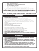
GENERAL WARNINGS: WARNING • • • • • • • • • • • • • • • • • • • • • • • • • • 3 Leak test all connections before first use, even if grill was purchased fully assembled and after each tank refill. Check the propane tank rubber seal for damage. Always check the grill and propane tank prior to each use as indicated in the “Checking for Leaks” & “Pre-Start Check List” sections of this manual. Never use natural gas in a unit designed for liquid propane gas.
• Grill is hot when in use. To avoid burns: • • • • • • DO NOT attempt to move the grill. Block the wheels so the unit does not accidentally move. Wear protective gloves or oven mitts. DO NOT touch any hot grill surfaces. DO NOT wear loose clothing or allow hair to come in contact with grill. Not for commercial use. DO NOT use this grill for anything other than its intended purpose. USE CAUTION AND COMMON SENSE WHEN OPERATING YOUR GAS GRILL.
LP GAS CYLINDER (TANK) SPECIFICATIONS: LP gas cylinder (not supplied with this grill) The LP (Liquid Propane) gas cylinder specifically designed to be used with this grill must be 12” (30.5 cm) diameter x 18” (45.7 cm) tall and have a 20 lb. (9.1 kg) capacity incorporating a Type 1 cylinder valve and an over-filling protection device (OPD). This grill is designed to fit Worthington, Manchester or SMPC brand 20 lb. (9.1 kg) cylinders.
LP GAS CYLINDER (TANK) RUBBER SEAL INSPECTION: • Inspect the propane tank valve rubber seal for cracks, wear or deterioration prior to use. A damaged rubber seal can cause a gas leak, possibly resulting in an explosion, fire or severe bodily harm. • Inspection should be done each time the propane tank is connected to the grill, has been refilled, exchanged or has not been used for more than 60 days. • Do not use a propane tank with a damaged rubber seal.
HOSE AND REGULATOR: Your grill is equipped with a Type 1 connection device with the following features: 1. The system will not allow gas flow from the cylinder until a positive connection to the valve has been made. Note: The cylinder valve and all grill burner knobs must be turned OFF before any connection is made or removed. 2. A regulator flow limiting device, when activated, restricts the flow of gas to 10 cubic feet per hour.
DANGER To prevent fire or explosion hazard: • DO NOT smoke or permit ignition sources in the area while conducting a leak test. • Perform test OUTDOORS in a well ventilated area that is protected from the wind. • Never perform a leak test with a match or open flame. • Never perform a leak test while the grill is in use or while grill is still hot. WHEN TO PERFORM A LEAK TEST: • • • • After assembling your grill and before lighting for the first time, even if purchased fully assembled.
PRE-START CHECK LIST: DANGER Property damage, bodily harm, severe burns, and death could result from failure to follow these safety steps. These steps should be performed after the grill has been assembled and prior to each use. DO NOT operate this grill until you have read and understand ALL of the warnings and instructions in this manual. • Ensure that the grill is properly assembled. • Inspect the gas supply hose for burns, chaffing, kinks, and proper routing before each use.
5. To light other burner, push and turn control knob to “HIGH”. 6. If burner does not ignite using the igniter, see “Match Lighting the Main Burners” section. 7. To turn off, turn each control knob clockwise until it locks in the “OFF” position. This does not turn off the gas flow from the cylinder. Note: If burner does not light or flame is too low, See “Trouble Shooting” section of the owners manual. MATCH LIGHTING THE MAIN BURNERS: Lighting Hole 1. Open lid before lighting. 2.
OPERATING THE GRILL: WARNING • • • • • • • Read and follow all warnings and instructions contained in the preceding sections of this manual. Never use charcoal, lava rocks or wood briquets in a gas grill. Flavoring chips must be contained in a metal smoking box to contain ash and prevent fires. DO NOT cover cooking grates or other components with aluminum foil, as this blocks ventilation and damage to grill or personal injury may occur. DO NOT leave your grill unattended while “ON” or in use.
TURNING OFF THE GRILL: 1. Turn off the cylinder valve. 2. Turn all burner control knobs to the “OFF” position. Note: Turn off LP cylinder first to prevent gas from being left in the system under pressure. CAUTION: • The cylinder valve should always be in the off, or closed, position when the grill is not in use. To turn off the cylinder valve, turn knob clockwise until it stops.
PROPER CARE & MAINTENANCE: WARNING: If a bristle brush is used to clean any of the cooking surfaces, ensure no loose bristles remain on the cooking surfaces prior to grilling as loose bristles may attach to food. CLEANING INTERIOR OF GRILL: • We recommend cleaning off food residue immediately after cooking by gently scrubbing grates with wire bristle brush and then turning burners to HIGH for approximately 5 minutes. WARNING: DO NOT leave grill unattended when grill is on.
BURNER ASSEMBLY/MAINTENANCE: • • Although your burners are constructed of stainless steel, they may corrode as a result of the extreme heat and acids from cooking foods. Regularly inspect the burners for cracks, abnormal holes, and other signs of corrosion damage. If found, replace the burner. DO NOT block ventilation areas in sides, back or cart compartment of grill. Burner tubes can become blocked by spiders and other insects building their nests.
BURNER ADJUSTMENT: WARNING • DO NOT attempt to adjust burner air shutter until grill has cooled down for approximately 30 minutes. Failure to do so could cause severe burns. • Normal flame should be soft blue with yellow tips between 1 in. - 2 in. when burner is on “HIGH”. Depending on elevation, burner air shutter may need to be adjusted to obtain correct air to fuel ratio.
TROUBLE SHOOTING: To see trouble shooting or assembly videos, visit us at: Problem Possible Cause Prevention/Cure Burner will not light LP gas tank valve is closed Make sure regulator is securely attached to the LP gas tank, turn LP gas tank valve to “OPEN” LP gas tank is low or empty Check if LP gas tank is empty. If empty, replace or refill. LP gas leak 1. Turn LP gas tank valve to “CLOSED” 2. Wait 5 minutes for gas to clear 3.
Problem Possible Cause Prevention/Cure Flame blows out High or gusting winds Do not use grill in high winds Low on LP gas Replace or refill LP gas tank Burner holes may be obstructed Refer to “Burner Assembly/Maintenance” instructions Flow limiting device tripped Refer to “Regulator Resetting Procedure” Grease buildup Clean all grill parts per “Proper Care and Maintenance” instructions Excess fat in meat Trim fat from meat before grilling Excessive cooking temperature Adjust (lower) cooking
ASSEMBLY INSTRUCTIONS: Make sure you have all items listed under PARTS LIST and PARTS CARD CONTENTS before you begin the installation process. PARTS CARD CONTAINS: Qty. 11 M5 X 10 mm Bolts (Black) 28 M6 X 12 mm Bolts (Black) 2 M6 Self-locking Nuts (Black) 4 M6 Shoulder Bolts (Black) 1 Wrench Qty.
READ ALL SAFETY WARNINGS & ASSEMBLY INSTRUCTIONS CAREFULLY BEFORE ASSEMBLING OR OPERATING YOUR GRILL. WE RECOMMEND TWO PEOPLE WORK TOGETHER WHEN ASSEMBLING THIS UNIT.
1 3 2 5 4 8 6 9 10 7 13 12 14 15 11 16 19 17 20 18 FOR COVERS, ACCESSORIES AND OTHER PRODUCTS, PLEASE VISIT US ONLINE AT: Inspect contents of the box to ensure all parts are included and undamaged.
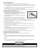
Choose a good, cleared assembly area and get a friend to help you put your grill together. Lay cardboard down to protect grill finish and assembly area. CAUTION: Some parts may contain sharp edges. Wear protective gloves if necessary. Step 1 Using sixteen M6 X 12 (black) bolts, attach the four swivel caster assemblies to the base. Step 2 Use six M5 X 10 mm bolts (black) to attach the left and right cart panels to the cart frame. Cart Frame NOTE: The two bolt holes face outward.
Front Cart Panel Step 3 Align the captive bolts on the left and right panels to the slots in the front panel and secure with eight M5 nuts. Step 4 Use five M5 X 10 mm bolts (black) to attach the cart assembly to the base. Step 5 Loosen the two pre-attached bolts from the cart braces (as illustrated below), place the heat shield on the cart brace and aligning the two bolts with the slots on the heat shield, then tighten the screws securely.
Note: Have someone assist you while performing Step 6. Step 6 Align the five bolts on the top of the cart assembly and the five holes at bottom of the grill body, use five wing nuts and washers to tighten the grill body to the cart assembly securely. Hose Assembly Step 7 Align the four holes on the hose assembly over the four preattached bolts on the firebox, insert the bolts through the holes and slide the hose assembly downward in place, then tighten the bolts securely.
Step 11 Attach the hood to the firebox using two hood hinge pins. Secure with two M6 self-locking nuts. Step 12 Attach the grease cup to the bracket which is at bottom of the grill body. Grease Cup Step 13 To attach the left and right side tables, slide the L slot of the side table onto the stub that is welded on the grill body, then use two M6 shoulder bolts (Black) to secure the side table.
Step 14 Attach the knobs to the valve stems. Knobs Warming Rack Step 15 Attach the warming rack to the firebox (as shown below). Place the heat tents and cooking grate in the grill body. Step 16 When folding the side table down, lift the side table up and turn it downward.
Brinkmann® 6230 (Assembled) 26
IMPORTANTES ADVERTENCIAS DE SEGURIDAD ES NUESTRO DESEO QUE ARME Y UTILICE SU PARRILLA EN LA FORMA MÁS SEGURA POSIBLE. EL PROPÓSITO DE ESTE SÍMBOLO DE ALERTA DE SEGURIDAD ES QUE USTED PRESTE ATENCIÓN A LOS POSIBLES PELIGROS CUANDO ARME Y UTILICE SU PARRILLA. ¡CUÁNDO VEA ESTE SÍMBOLO DE ALERTA DE SEGURIDAD ATENCIÓN A LA INFORMACIÓN A CONTINUACIÓN! PRESTE ESPECIAL LEA DETENIDAMENTE TODAS LAS ADVERTENCIAS DE SEGURIDAD E INSTRUCCIONES ANTES DE ARMAR Y USAR LA PARRILLA. PELIGRO SI HUELE GAS: 1.
TABLA DE CONTENIDOS: Advertencias Generales . . . . . . . . . . . . . . . . . . . . . . . . . . . . . . . . . . . . . . 29-30 Especificaciones e Instalación del Cilindro (Tanque) de Gas LP . . . . . . 30-32 Especificaciones e Instalación de la Manguera y el Regulador. . . . . . . . 32-33 Pruebas de Detección de Fugas . . . . . . . . . . . . . . . . . . . . . . . . . . . . . . . 33-34 Lista de Comprobación Previa al Arranque . . . . . . . . . . . . . . . . . . . . . . . . . . 35 Instrucciones de Encendido .
ADVERTENCIAS GENERALES: ADVERTENCIA • • • • • • • • • • • • • • • • • • • • • • • • • 29 Antes de usar la parrilla por primera vez, pruebe todas las conexiones en busca de fugas, incluso si compró la parrilla totalmente armada y cada vez que vuelva a cargar el tanque. Inspeccione el sello de caucho del tanque de propano en busca de daños.
• • NO almacene artículos en el carrito que puedan prenderse fuego o dañar la parrilla (como químicos o suministros para piscinas, manteles, trozos de madera). Cuando la parrilla se usa, está caliente. Para evitar quemaduras: • • • • • • NO intente mover la parrilla. Trabe las ruedas de manera que la unidad no se mueva accidentalmente. Use guantes protectores o manoplas para horno. NO toque ninguna de las superficies calientes de la parrilla.
ESPECIFICACIONES DEL CILINDRO (TANQUE) DE GAS LP: Cilindro de gas LP (no suministrado con esta parrilla) El cilindro de gas LP (propano líquido) específicamente diseñado para usarse con esta parrilla debe tener 12” (30.5 cm) de diámetro × 18” (45.7 cm) de alto y una capacidad de 20 lb (9.1 kg), con una válvula del cilindro Tipo 1 y un dispositivo de protección contra sobrecarga (OPD). Esta parrilla está diseñada para usarse con cilindros de 20 lb (9.1 kg) de marca Worthington, Manchester o SMPC.
INSPECCIÓN DEL SELLO DE CAUCHO DEL CILINDRO (TANQUE) DE GAS LP: • Antes de usar, inspeccione el sello de caucho de la válvula del tanque de propano en busca de fisuras, desgaste o signos de deterioro. Un sello de caucho dañado puede causar una fuga de gas, lo que posiblemente derive en una explosión, un incendio o lesiones corporales graves.
REGULADOR Y MANGUERA: La parrilla viene equipada con un dispositivo de conexión Tipo 1 con las siguientes características: 1. El sistema no permitirá la circulación de gas desde el cilindro hasta que se establezca una conexión positiva a la válvula. Nota: La válvula del cilindro y todas las perillas de los quemadores de la parrilla deben estar cerradas antes de realizar o quitar cualquier conexión. 2.
PELIGRO Para prevenir los peligros vinculados con los incendios o explosiones: • NO fume ni permita que haya fuentes de ignición en la zona donde lleve a cabo una prueba de detección de fugas. • Realice la prueba en un área bien ventilada AL AIRE LIBRE, protegida contra el viento. • Nunca lleve a cabo una prueba de detección de fugas con un fósforo o una llama. • Nunca lleve a cabo una prueba de detección de fugas con la parrilla en uso o aún caliente.
LISTA DE COMPROBACIÓN PREVIA AL ARRANQUE: PELIGRO Si no se siguen estos pasos, pueden ocurrir daños a la propiedad, lesiones corporales, quemaduras graves y la muerte. Estos pasos deben llevarse a cabo después de que la parrilla se armó y antes de cada uso. NO use esta parrilla hasta haber leído y entendido TODAS las advertencias y las instrucciones incluidas en este manual. • • • • • • • Asegúrese de que la parrilla esté correctamente armada.
5. Para encender otra hornilla, gire la perilla de control a “ALTO”. 6. Si no se enciende la hornilla al usar el encendedor; consulte la sección de “Encendido de los Quemadores Principales con Fósforos”. 7. Para apagar, gire cada perilla de control en sentido horario hasta que se trabe en la posición “APAGADO”. Esto no apaga el flujo de gas del cilindro. Nota: Si el quemador no se enciende o la llama es muy baja, consulte la sección “Solución de Problemas” del manual del propietario.
FUNCIONAMIENTO DE LA PARRILLA: ADVERTENCIA • • • • • • • Lea y siga todas las advertencias y las instrucciones incluidas en las secciones anteriores de este manual. Nunca use carbón, rocas volcánicas o briquetas de madera en una parrilla a gas. Los copos saborizantes deben colocarse en una caja para ahumar de metal para contener las cenizas y evitar incendios.
APAGADO DE LA PARRILLA: 1. Cierre la válvula del cilindro. 2. Coloque todas las perillas de control de los quemadores en la posición “APAGADO”. Nota: Primero cierre el cilindro de gas LP para evitar que quede gas en el sistema bajo presión. PRECAUCIÓN: • Cuando la parrilla no se usa, la válvula del cilindro debe estar siempre en la posición “APAGADO” o cerrada. Para cerrar la válvula del cilindro, gire la perilla hacia la derecha hasta que haga tope.
CUIDADO Y MANTENIMIENTO ADECUADOS: ADVERTENCIA: Si usa un cepillo de cerdas para limpiar cualquiera de las superficies para cocinar, asegúrese de que no queden cerdas sueltas sobre dichas superficies antes de usar la parrilla, ya que las cerdas sueltas se pueden pegar a la comida.
CONJUNTO DE LOS QUEMADORES/ MANTENIMIENTO: • • Aunque los quemadores están hechos de acero inoxidable, pueden corroerse como resultado del calor extremo y de los ácidos derivados de la cocción de comida. Periódicamente, inspeccione los quemadores en busca de fisuras, orificios anormales y otros signos de deterioro por corrosión. De encontrarlos, reemplace el quemador. NO bloquee las áreas de ventilación en los laterales, la parte posterior o el compartimiento del carrito de la parrilla.
AJUSTE DE LOS QUEMADORES: ADVERTENCIA • NO intente ajustar el obturador de aire de los quemadores hasta que la parrilla se haya enfriado durante aproximadamente 30 minutos. Si no cumple con esta indicación, puede sufrir quemaduras graves. • Las llamas normales deben ser de color azul claro con puntas amarillas, y deben ser de entre 1” y 2” cuando el quemador está en la posición “ALTO”.
SOLUCIÓN DE PROBLEMAS: Para ver videos de montaje o solución de problemas, visítenos en: Problema Causa posible Prevención/Cuidado El quemador no enciende La válvula del tanque de gas LP está cerrada Cerciórese de que el regulador esté conectado al tanque de gas LP con firmeza; gire la válvula del tanque de gas LP a la posición “ABIERTA” El nivel del tanque de gas LP es bajo o el tanque está vacío Verifique si el tanque de gas LP está vacío.
Problema Causa posible Prevención/Cuidado La llama es amarilla o anaranjada Es posible que el quemador nuevo contenga aceites residuales de la fabricación Encienda la parrilla durante 15 minutos en la posición “ALTO” con la tapa cerrada Es posible que haya telarañas o nidos de insectos en los tubos venturi de los quemadores.
SUGERENCIAS PARA COCINAR CON LA PARRILLA: HIGIENE: • • • • Siempre lávese las manos minuciosamente con jabón y agua caliente antes de manipular la comida y después de manipular carne vacuna o de pollo cruda, o mariscos/pescados.
INSTRUCCIONES DE ARMADO: Verifique que tiene todos los artículos indicados en la LISTA DE PARTES y en el CONTENIDO DE LA BOLSA DE PARTES antes de comenzar con el proceso de instalación. LA BOLSA DE PARTES INCLUIRÁ LO SIGUIENTE: Cant. Cant.
LEA DETENIDAMENTE TODAS LAS ADVERTENCIAS DE SEGURIDAD E INSTRUCCIONES ANTES DE ARMAR Y USAR LA PARRILLA RECOMENDAMOS QUE ESTA UNIDAD SEA ARMADA POR DOS PERSONAS.
1 3 2 5 4 8 6 9 10 7 13 12 14 15 11 16 19 17 20 18 PARA CUBIERTAS, ACCESORIOS Y OTROS PRODUCTOS, FAVOR DE VISITARNOS POR LA RED MUNDIAL EN: (La prueba de compra se requiere.) Inspeccione el contenido de la caja para verificar que todas las partes estén incluidas e intactas.
Elija un lugar adecuado y despejado para armar la parrilla y pídale a un amigo que le ayude. Tienda cartón sobre el suelo para proteger el acabado de la parrilla y el área de armado. PRECAUCIÓN: Algunas partes pueden tener bordes afilados. Póngase guantes de protección si es necesario. Paso 1 Usando dieciséis pernos M6 x 12 mm (negros), una los cuatro ensamblados de ruedas a la base. Marco del Carro Paso 2 Use seis pernos M5 x 10 mm (negros) para unir los paneles izquierdo y derecho al marco del carro.
Panel Frontal Paso 3 Alinee los pernos asegurados en los paneles izquierdo y derecho a las ranuras en el panel frontal y asegúrelos con ocho tuercas M5. Paso 4 Use cinco pernos M5 x 10 mm (negros) para unir el ensamblado del carro a la base. Paso 5 Afloje los dos pernos previamente ensamblados en los soportes del carro (tal como se ilustra), coloque el escudo térmico en el soporte del carro y alinee los dos pernos en las ranuras del escudo térmico, luego apriete los tornillos con seguridad.
Nota: Use la asistencia de alguien mientras ejecuta el Paso 6. Paso 6 Ensamblado de la Manguera Alinee los cinco pernos en la parte superior del ensamblado del carro y los cinco agujeros en la parte inferior del cuerpo de la parrilla, use cinco tuercas de mariposa y arandelas para apretar el cuerpo de la parrilla al ensamblado del carro con seguridad.
Paso 11 Una la tapa a la caja de fuego usando dos pasadores de bisagra de la tapa. Asegúrelos con dos tuercas de bloqueo M6. Paso 12 Una el recipiente para grasa al soporte que está en la parte inferior del cuerpo de la parrilla. Recipiente para Grasa Paso 13 Para unir las mesas laterales izquierda y derecha, deslice la ranura en forme de “L” de la mesa lateral en el colilla soldada al cuerpo de la parrilla, luego use dos pernos de hombro M6 (negros) para asegurar la mesa lateral.
Paso 14 Una las perillas a los vástagos de válvula. Perillas Rejilla para Calentar Rejilla para Cocinar Paso 15 Una la rejilla para calentar a la caja de fuego (como se ilustra). Coloque las placas térmicas y la rejilla para cocinar en el cuerpo de la parrilla. Placas Térmicas Paso 16 Cuando doble la mesa lateral hacia abajo, levante la mesa lateral y doble hacia abajo.
Brinkmann® 6230 (Armada) 53
FOR COVERS, ACCESSORIES AND OTHER PRODUCTS, PLEASE VISIT US ONLINE AT: PARA CUBIERTAS, ACCESORIOS Y OTROS PRODUCTOS, FAVOR DE VISITARNOS POR LA RED MUNDIAL EN: WARRANTY The Brinkmann Corporation warrants to the original purchaser that the Brinkmann® 2 Burner Portico Gas Grill is free from defects due to workmanship or materials for: Ten-year: on stainless steel burners Three-year: on all other stainless steel parts One-year: on valves, frame, housing, cart, igniter, cooking grates and other related parts T