Dual Sear 5 Burner Gas Grill Parrilla a Gas de 5 Quemadoras con Doble Quemador para Dorar OWNER’S MANUAL / MANUAL DEL PROPIETARIO ASSEMBLY AND OPERATING INSTRUCTIONS INSTRUCCIONES DE ARMADO Y OPERACIÓN SAVE THIS MANUAL FOR FUTURE REFERENCE GUARDE ESTE MANUAL PARA REFERENCIA FUTURA Model / Modelo 810-6630-S NOTICE TO INSTALLER: LEAVE THESE INSTRUCTIONS WITH THE GRILL OWNER FOR FUTURE REFERENCE. AVISO PARA EL INSTALADOR: ENTREGUE ESTAS INSTRUCCIONES AL PROPIETARIO DE LA PARRILLA PARA REFERENCIA FUTURA.
IMPORTANT SAFETY WARNINGS WE WANT YOU TO ASSEMBLE AND USE YOUR GRILL AS SAFELY AS POSSIBLE. IS TO ATTRACT YOUR ATTENTION THE PURPOSE OF THIS SAFETY ALERT SYMBOL TO POSSIBLE HAZARDS AS YOU ASSEMBLE AND USE YOUR GRILL. WHEN YOU SEE THE SAFETY ALERT SYMBOL PAY CLOSE ATTENTION TO THE INFORMATION WHICH FOLLOWS! READ ALL SAFETY WARNINGS AND INSTRUCTIONS CAREFULLY BEFORE ASSEMBLING AND OPERATING YOUR GRILL. DANGER IF YOU SMELL GAS: 1. Shut off gas to the appliance. 2. Extinguish any open flame. 3. Open lid. 4.
TABLE OF CONTENTS: General Warnings . . . . . . . . . . . . . . . . . . . . . . . . . . . . . . . . . . . . . . . . . . . . 3-4 LP Gas Cylinder (Tank) Specifications and Installation . . . . . . . . . . . . . . . . 4-6 Hose & Regulator Specifications and Installation . . . . . . . . . . . . . . . . . . . . 6-7 Leak Testing. . . . . . . . . . . . . . . . . . . . . . . . . . . . . . . . . . . . . . . . . . . . . . . . . 7-8 Pre-start Check List . . . . . . . . . . . . . . . . . . . . . . . . . . . . . . . . .
GENERAL WARNINGS: WARNING • • • • • • • • • • • • • • • • • • • • • • • • • • 3 Leak test all connections before first use, even if grill was purchased fully assembled and after each tank refill. Check the propane tank rubber seal for damage. Always check the grill and propane tank prior to each use as indicated in the “Checking for Leaks” & “Pre-Start Check List” sections of this manual. Never use natural gas in a unit designed for liquid propane gas.
• Grill is hot when in use. To avoid burns: • • • • • • DO NOT attempt to move the grill. Block the wheels so the unit does not accidentally move. Wear protective gloves or oven mitts. DO NOT touch any hot grill surfaces. DO NOT wear loose clothing or allow hair to come in contact with grill. Not for commercial use. DO NOT use this grill for anything other than its intended purpose. USE CAUTION AND COMMON SENSE WHEN OPERATING YOUR GAS GRILL.
LP GAS CYLINDER (TANK) SPECIFICATIONS: LP gas cylinder (not supplied with this grill) The LP (Liquid Propane) gas cylinder specifically designed to be used with this grill must be 12” (30.5 cm) diameter x 18” (45.7 cm) tall and have a 20 lb. (9.1 kg) capacity incorporating a Type 1 cylinder valve and an over-filling protection device (OPD). This grill is designed to fit Worthington, Manchester or SMPC brand 20 lb. (9.1 kg) cylinders.
LP GAS CYLINDER (TANK) RUBBER SEAL INSPECTION: • Inspect the propane tank valve rubber seal for cracks, wear or deterioration prior to use. A damaged rubber seal can cause a gas leak, possibly resulting in an explosion, fire or severe bodily harm. • Inspection should be done each time the propane tank is connected to the grill, has been refilled, exchanged or has not been used for more than 60 days. • Do not use a propane tank with a damaged rubber seal.
HOSE AND REGULATOR: Your grill is equipped with a Type 1 connection device with the following features: 1. The system will not allow gas flow from the cylinder until a positive connection to the valve has been made. Note: The cylinder valve and all grill burner knobs must be turned OFF before any connection is made or removed. 2. A regulator flow limiting device, when activated, restricts the flow of gas to 10 cubic feet per hour.
DANGER To prevent fire or explosion hazard: • DO NOT smoke or permit ignition sources in the area while conducting a leak test. • Perform test OUTDOORS in a well ventilated area that is protected from the wind. • Never perform a leak test with a match or open flame. • Never perform a leak test while the grill is in use or while grill is still hot. WHEN TO PERFORM A LEAK TEST: • • • • After assembling your grill and before lighting for the first time, even if purchased fully assembled.
PRE-START CHECK LIST: DANGER Property damage, bodily harm, severe burns, and death could result from failure to follow these safety steps. These steps should be performed after the grill has been assembled and prior to each use. DO NOT operate this grill until you have read and understand ALL of the warnings and instructions in this manual. • Ensure that the grill is properly assembled. • Inspect the gas supply hose for burns, chaffing, kinks, and proper routing before each use.
MATCH LIGHTING THE MAIN BURNERS: Lighting Hole 1. Open lid before lighting. 2. Turn the burner control knobs to “OFF”. 3. Place a paper match in the end of the matchlighter. Strike the match and place through lighting hole in the left hand side of the grill to approximately 1/2” (1 to 2 cm) from the burner. 4. Turn on the FAR LEFT burner control knob to the “HIGH” position. The burner should light within 5 seconds. 5.
6. To turn off, turn control knob clockwise until it locks in the “OFF” position. This does not turn off the gas flow from the cylinder. Note: If burner does not light or flame is too low, See “Trouble Shooting” section of the owners manual. MATCH LIGHTING THE SEAR BURNER: 1. 2. 3. 4. Open the lid to the sear burner before lighting. Make sure control knob is in the “OFF” position. Strike and carefully place a match approximately 1/2” (1 to 2 cm) from the sear burner.
CONTROLLING FLARE-UPS/GREASE FIRES: • • • • • Flare-ups are a part of cooking meats on a gas grill. This adds to the unique flavor of cooking on a gas grill. Use caution when opening the lid as sudden flare-ups may occur. Excessive flare-ups can over-cook your food and cause a dangerous situation for you and your grill. Excessive flare-ups result from the build-up of grease in your grill. If this should occur, DO NOT pour water onto the flames.
USING OTHER FEATURES OF THE GRILL: WARNING • • • • • • Read instructions on lighting your grill to light the side burner. Never close the side burner cover when the burner is lit. Use a 10” diameter pot or smaller that does NOT have an extended handle when cooking on the side burner. Center pot over burner. Never place more than 15 pounds on the side burner. The side burner is not constructed to hold weight exceeding 15 pounds.
RUST: • • • Discoloration, rust and rust pits can occur as a result of high cooking temperatures, acidic marinades, grease fires and exposure to coastal climates or other natural elements. Rust spots on the interior surface can be buffed, cleaned, then lightly coated with vegetable oil or vegetable oil spray to minimize rusting. Never use cleaners containing chlorine or store swimming pool supplies or chemicals in cart compartment as chlorine promotes rust.
BURNER ADJUSTMENT: WARNING • DO NOT attempt to adjust burner air shutter until grill has cooled down for approximately 30 minutes. Failure to do so could cause severe burns. • Normal flame should be soft blue with yellow tips between 1 in. - 2 in. when burner is on “HIGH”. Depending on elevation, burner air shutter may need to be adjusted to obtain correct air to fuel ratio.
TROUBLESHOOTING: To see trouble shooting or assembly videos, visit us at: Problem Possible Cause Prevention/Cure Burner will not light LP gas tank valve is closed Make sure regulator is securely attached to the LP gas tank, turn LP gas tank valve to “OPEN” LP gas tank is low or empty Check if LP gas tank is empty. If empty, replace or refill. LP gas leak 1. Turn LP gas tank valve to “CLOSED” 2. Wait 5 minutes for gas to clear 3.
Problem Possible Cause Prevention/Cure Flame blows out High or gusting winds Do not use grill in high winds Low on LP gas Replace or refill LP gas tank Burner holes may be obstructed Refer to “Burner Assembly/Maintenance” instructions Flow limiting device tripped Refer to “Regulator Resetting Procedure” Grease buildup Clean all grill parts per “Proper Care and Maintenance” instructions Excess fat in meat Trim fat from meat before grilling Excessive cooking temperature Adjust (lower) cooking
READ ALL SAFETY WARNINGS & ASSEMBLY INSTRUCTIONS CAREFULLY BEFORE ASSEMBLING OR OPERATING YOUR GRILL. ASSEMBLY INSTRUCTIONS: Make sure you have all items listed under PARTS LIST and PARTS BAG CONTENTS before you begin the installation process. Your Parts Bag will include: Qty.
WE RECOMMEND TWO PEOPLE WORK TOGETHER WHEN ASSEMBLING THIS UNIT.
2 1 4 3 6 7 5 10 11 9 8 12 16 14 13 13 20 18 21 19 17 23 22 27 26 24 25 30 29 28 31 32 FOR GRILL REPLACEMENT PARTS, COVERS & ACCESSORIES, PLEASE VISIT US ONLINE AT (Proof of purchase will be required.) Inspect contents of the box to ensure all parts are included and undamaged.
Choose a good, cleared assembly area and get a friend to help you put your grill together. Lay cardboard down to protect grill finish and assembly area. CAUTION: Some parts may contain sharp edges. Wear protective gloves if necessary. Non Locking Swivel Caster Non Swivel Caster Locking Swivel Caster Non Swivel Locking Caster Front Step 1 Attach casters to the bottom of cart base using eight M6 X 12 mm bolts (black) and eight star washers as illustrated.
Step 4 Attach the upper cart brace using four M6 X 12 mm bolts (black). Step 5 Insert tank block rack brace through the holes in the tank block rack. Secure with two M6 wing nuts (Figure 1). Insert tank block rack hooks into rack support keyholes on right side cart panel. Slide hooks toward the side panel (Figure 2). Align the holes in each foot of tank block rack with the corresponding holes in the cart base. Secure with two M5 X 10 mm bolts (black).
Right Door Assembly Left Door Assembly Step 7 Attach left side door by inserting the pins in the bottom the door into the cart base (Figure 1). Then, align the hole at the top of the door with the hole in the upper cart brace and insert one door hinge pin through both holes (Figure 2). Repeat for other door. Door Hinge Pin Figure 1 Note: When performing Step 8, lift grill body from front and rear panels to avoid injury to hands and fingers.
Step 9 Install knobs onto valve stems. The dual sear knob (only knob with circuitry) must be inserted on sear burner valve stem. Dual Sear Knob Step 10 Attach front panel to left side table by inserting pre-attached bolts on the front panel into the keyholes on side table. Slide into smaller part of keyhole. Tighten bolts securely. Step 11 Attach front panel to side burner by inserting pre-attached bolts on the front panel into the keyholes on side burner assembly. Slide into smaller part of keyhole.
Step 12 Attach left side table to left side of cart frame assembly. Place table over pre-attached bolts and slide toward back of grill, then tighten securely. Fasten side table front panel to grill body with one M6 X 12 mm bolt (black). Bolt Step 13 Attach right side burner assembly to right side of cart frame assembly. Place table over pre-attached bolts and slide toward back of grill, then tighten securely. Fasten side burner assembly front panel to grill body with one M6 X 12 mm bolt (black).
Figure 1 Side Burner Step 14 To install the side burner, remove the pre-attached wing nut and M4 washer on the side burner and install the side burner (Figure 1). Attach one M4 bolt (silver) to secure the tip of the side burner (Figure 2). Attach one M4 X 10 mm bolt (silver) from the top of the side burner to secure in place (Figure 3). Attach two M4 washers and one M4 nut and one wing nut to secure the side burner (Figure 4).
Side Burner Grate Step 16 Place the side burner grate onto the side burner table. Step 17 Slide the grease tray onto the tracks located behind and underneath the grill body assembly. Step 18 Hang grease cup from the grease tray. Make sure to slide cup onto tracks as illustrated.
Step 19 Sear Zone Divider Plate Warming Rack Insert the sear zone divider plate into channel as shown. Step 20 Place the heat distribution plates and sear burner heat distribution plate on lower level of grill body assembly directly above burners. Cooking Grates Heat Distribution Plates Sear Burner Cooking Grill Sear Burner Heat Distribution Plate Step 21 Place cooking grills and sear burner cooking grill on support ribs directly above heat distribution plates.
Brinkmann® 6630 (Assembled) 29
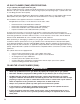
REPLACING THE LED BATTERY IN THE SEAR BURNER CONTROL KNOB Step 2 Step 1 Battery Tab Loosen screw to battery tab using a screwdriver. Rotate the battery tab to gain access to the battery pack. + Step 4 Step 3 Remove the old battery pack from the sear burner control knob. Replace with a new battery pack. Switch Step 6 Step 5 Reposition the battery tab back to its original position. Secure the battery tab using a screwdriver. Tighten securely.
IMPORTANTES ADVERTENCIAS DE SEGURIDAD ES NUESTRO DESEO QUE ARME Y UTILICE SU PARRILLA EN LA FORMA MÁS SEGURA POSIBLE. EL PROPÓSITO DE ESTE SÍMBOLO DE ALERTA DE SEGURIDAD ES QUE USTED PRESTE ATENCIÓN A LOS POSIBLES PELIGROS CUANDO ARME Y UTILICE SU PARRILLA. PRESTE ESPECIAL ¡CUÁNDO VEA ESTE SÍMBOLO DE ALERTA DE SEGURIDAD ATENCIÓN A LA INFORMACIÓN A CONTINUACIÓN! LEA DETENIDAMENTE TODAS LAS ADVERTENCIAS DE SEGURIDAD E INSTRUCCIONES ANTES DE ARMAR Y USAR LA PARRILLA. PELIGRO SI HUELE GAS: 1.
TABLA DE CONTENIDOS: Advertencias Generales . . . . . . . . . . . . . . . . . . . . . . . . . . . . . . . . . . . . . . 33-34 Especificaciones e Instalación del Cilindro (Tanque) de Gas LP . . . . . . 34-36 Especificaciones e Instalación de la Manguera y el Regulador. . . . . . . . 36-37 Pruebas de Detección de Fugas . . . . . . . . . . . . . . . . . . . . . . . . . . . . . . . 37-38 Lista de Comprobación Previa al Arranque . . . . . . . . . . . . . . . . . . . . . . . . . . 39 Instrucciones de Encendido .
ADVERTENCIAS GENERALES: ADVERTENCIA • • • • • • • • • • • • • • • • • • • • • • • • • 33 Antes de usar la parrilla por primera vez, pruebe todas las conexiones en busca de fugas, incluso si compró la parrilla totalmente armada y cada vez que vuelva a cargar el tanque. Inspeccione el sello de caucho del tanque de propano en busca de daños.
• • • NO almacene artículos en el carrito que puedan prenderse fuego o dañar la parrilla (como químicos o suministros para piscinas, manteles, trozos de madera). Cuando la parrilla se usa, está caliente. Para evitar quemaduras: • NO intente mover la parrilla. • Trabe las ruedas de manera que la unidad no se mueva accidentalmente. • Use guantes protectores o manoplas para horno. • NO toque ninguna de las superficies calientes de la parrilla.
ESPECIFICACIONES DEL CILINDRO (TANQUE) DE GAS LP: Cilindro de gas LP (no suministrado con esta parrilla) El cilindro de gas LP (propano líquido) específicamente diseñado para usarse con esta parrilla debe tener 12” (30.5 cm) de diámetro × 18” (45.7 cm) de alto y una capacidad de 20 lb (9.1 kg), con una válvula del cilindro Tipo 1 y un dispositivo de protección contra sobrecarga (OPD). Esta parrilla está diseñada para usarse con cilindros de 20 lb (9.1 kg) de marca Worthington, Manchester o SMPC.
INSPECCIÓN DEL SELLO DE CAUCHO DEL CILINDRO (TANQUE) DE GAS LP: • Antes de usar, inspeccione el sello de caucho de la válvula del tanque de propano en busca de fisuras, desgaste o signos de deterioro. Un sello de caucho dañado puede causar una fuga de gas, lo que posiblemente derive en una explosión, un incendio o lesiones corporales graves.
REGULADOR Y MANGUERA: La parrilla viene equipada con un dispositivo de conexión Tipo 1 con las siguientes características: 1. El sistema no permitirá la circulación de gas desde el cilindro hasta que se establezca una conexión positiva a la válvula. Nota: La válvula del cilindro y todas las perillas de los quemadores de la parrilla deben estar cerradas antes de realizar o quitar cualquier conexión. 2.
PELIGRO Para prevenir los peligros vinculados con los incendios o explosiones: • NO fume ni permita que haya fuentes de ignición en la zona donde lleve a cabo una prueba de detección de fugas. • Realice la prueba en un área bien ventilada AL AIRE LIBRE, protegida contra el viento. • Nunca lleve a cabo una prueba de detección de fugas con un fósforo o una llama. • Nunca lleve a cabo una prueba de detección de fugas con la parrilla en uso o aún caliente.
LISTA DE COMPROBACIÓN PREVIA AL ARRANQUE: PELIGRO Si no se siguen estos pasos, pueden ocurrir daños a la propiedad, lesiones corporales, quemaduras graves y la muerte. Estos pasos deben llevarse a cabo después de que la parrilla se armó y antes de cada uso. NO use esta parrilla hasta haber leído y entendido TODAS las advertencias y las instrucciones incluidas en este manual. • • • • • • • Asegúrese de que la parrilla esté correctamente armada.
ENCENDIDO DE LOS QUEMADORES PRINCIPALES CON FÓSFOROS: Orificio para Encendido 1. Abra la tapa antes de encender. 2. Gire las perillas de control de quemadores a posición “APAGADO”. 3. Coloque un cerillo de papel en el extremo de encendedor con cerillo. Prenda el cerillo y colóquelo a través del agujero de encendido en el lado izquierdo de la parrilla aproximadamente a 1/2” pulgada (1 a 2 cm) de la quemador. 4. Gire la perilla de control de quemador del EXTREMO IZQUIERDA a “ALTO”.
5. 6. Si no se enciende el quemador al usar el encendedor, consulte la sección de “Encendido de las quemador parra dorar con un cerillo”. Para apagar, gire cada perilla de control en sentido horario hasta que se trabe en la posición “APAGADO”. Esto no apaga el flujo de gas del cilindro. Nota: Si el quemador no se enciende o la llama es muy baja, consulte la sección “Solución de Problemas” del manual del propietario. ENCENDIDO DEL QUEMADOR PARA DORAR CON UN CERILLO: 1. 2. 3. 4. 5.
• • • • Si ocurre un incendio de grasa, deje la tapa abierta, gire las perillas de los quemadores a la posición “APAGADO” y cierre la válvula del cilindro de gas LP. Si es posible, reubique la comida en una sección diferente de la rejilla para cocinar y deje que la grasa arda hasta consumirse o apague las llamas con bicarbonato. Si ocurre un incendio de grasa con la tapa cerrada, deje la tapa cerrada, ya que una corriente de aire repentina puede aumentar las llamas.
USO DE OTRAS FUNCIONES DE LA PARRILLA: ADVERTENCIA • • • • • • Lea las instrucciones de encendido de la parrilla para encender el quemador lateral. Nunca cierre la cubierta del quemador lateral cuando el quemador esté encendido. Cuando cocine en el quemador lateral, use una olla de 10” de diámetro o más pequeña SIN un mango extendido. Centre la ola en el quemador. Nunca coloque más de 15 libras sobre el quemador lateral. El quemador lateral no está construido para soportar un peso superior a 15 libras.
ÓXIDO: • Como resultado de las altas temperaturas de cocción, los adobos ácidos, los incendios de grasa, y la exposición a climas costeros u a otros elementos naturales, puede observarse decoloración, óxido o picaduras de óxido. • Las manchas de óxido en la superficie interior se pueden pulir, limpiar y cubrir ligeramente con aceite vegetal o con aceite vegetal en aerosol para minimizar la oxidación.
AJUSTE DE LOS QUEMADORES: ADVERTENCIA • NO intente ajustar el obturador de aire de los quemadores hasta que la parrilla se haya enfriado durante aproximadamente 30 minutos. Si no cumple con esta indicación, puede sufrir quemaduras graves. • Las llamas normales deben ser de color azul claro con puntas amarillas, y deben ser de entre 1” y 2” cuando el quemador está en la posición “ALTO”.
SOLUCIÓN DE PROBLEMAS: Para ver videos de montaje o solución de problemas, visítenos en: Problema Causa posible Prevención/Cuidado El quemador no enciende La válvula del tanque de gas LP está cerrada Cerciórese de que el regulador esté conectado al tanque de gas LP con firmeza; gire la válvula del tanque de gas LP a la posición “ABIERTA” El nivel del tanque de gas LP es bajo o el tanque está vacío Verifique si el tanque de gas LP está vacío.
Problema Causa posible Prevención/Cuidado La llama es amarilla o anaranjada Es posible que el quemador nuevo contenga aceites residuales de la fabricación Encienda la parrilla durante 15 minutos en la posición “ALTO” con la tapa cerrada Es posible que haya telarañas o nidos de insectos en los tubos venturi de los quemadores.
SUGERENCIAS PARA COCINAR CON LA PARRILLA: HIGIENE: • • • • Siempre lávese las manos minuciosamente con jabón y agua caliente antes de manipular la comida y después de manipular carne vacuna o de pollo cruda, o mariscos/pescados.
INSTRUCCIONES DE ARMADO: LEA DETENIDAMENTE TODAS LAS ADVERTENCIAS DE SEGURIDAD E INSTRUCCIONES ANTES DE ARMAR Y USAR LA PARRILLA RECOMENDAMOS QUE ESTA UNIDAD SEA ARMADA POR DOS PERSONAS Se necesitan las siguientes herramientas para armar esta Parrilla a Gas con Doble Quemador para Abrasar: • Destornillador de Cabeza Phillips • Llave de Tuercas Hexagonales LISTA DE PARTES: 1 1 Montaje del Cuerpo de la Parrilla 2 1 Meza Lateral Izquierda 3 1 Meza Lateral Derecha 4 1 Panel Frontal de la Meza Lateral Izquierda
2 1 4 3 6 7 5 10 11 9 8 12 16 14 13 13 20 18 21 19 17 23 22 27 26 24 25 30 29 28 31 32 PARA ENCONTRAR PARTES DE REEMPLAZO PARA SU PARRILLA, CUBIERTAS Y ACCESORIOS, FAVOR DE VISITARNOS AL (La prueba de compra se requiere.) Inspeccione el contenido de la caja para verificar que todas las partes estén incluidas e intactas.
Verifique que tiene todos los artículos indicados en la LISTA DE PARTES y en el CONTENIDO DE LA BOLSA DE PARTES antes de comenzar con el proceso de instalación. La bolsa de partes incluirá lo siguiente: Cant.
Ruedilla Giratoria que No Traba Ruedilla No Giratoria Ruedilla Giratoria que Traba Ruedilla No Giratoria que Traba Elija un lugar adecuado y despejado para armar la parrilla y pídale a un amigo que le ayude. Tienda cartón sobre el suelo para proteger el acabado de la parrilla y el área de armado. CUIDADO: Algunas partes pueden Frente tener bordes afilados. Póngase guantes de protección si es necesario.
Paso 4 Fije el apoyo superior del carro con cuatro pernos M6 X 12 mm (negros). Paso 5 Inserte el soporte de las rejillas de bloqueo del tanque en los agujeros in las rejillas de bloqueo del tanque. Asegúrelo con dos tuercas de ala M6 (Figura 1). Inserte los ganchos de las rejillas de bloqueo del tanque en los agujeros de soporte en la parte derecha del panel del carro. Deslice los ganchos hacia el panel lateral (Figura 2).
Montaje de la Puerta Derecha Montaje de la Puerta Izquierda Paso 7 Una la puerta izquierda insertando el pasador en la parte inferior de la puerta y en la base del carro (Figura 1). Luego, alinee el agujero en la parte superior de la puerta con el agujero en el soporte superior del carro e inserte un pasador de bisagra por ambos agujeros (Figura 2). Repita para la otra puerta.
Paso 9 Instale las perillas en los vástagos de válvula. La perilla de doble dorador (la unica perilla con circuito) debe ser insertada en el vástago de válvula del dorador. Perilla de Doble Dorador Paso 10 Anexe el panel frontal de la mesa lateral izquierda insertando los pernos preanexados del panel frontal dentro de los orificios de la mesa lateral. Deslice en la parte pequeña del agujero. Luego ajuste los pernos de manera segura.
Paso 12 Fije la mesa lateral izquierda al lateral izquierdo del montaje del armazón del carro. Coloque la mesa sobre los pernos previamente fijados y deslícela hacia la parte trasera de la parrilla; luego ajuste los pernos firmemente. Ajuste el panel frontal de la mesa lateral al cuerpo de la parrilla con un perno M6 X 12 mm (negro). Perno Paso 13 Fije el montaje del quemador lateral derecho al lateral derecho del montaje del armazón del carro.
Paso 14 Figura 1 Para instalar el quemador lateral, quite la tuerca de ala y arandela M4 pre-atadas en el quemador lateral e instale el quemador lateral (Figura 1). Fije un perno M4 (plateado) para asegurar la punta del quemador lateral (Figura 2). Adjunte un perno M4 X 10 mm (plateado) de la parte superior del quemador lateral para asegurar en su lugar (Figura 3). Coloque las dos arandelas M4, una tuerca M4 y una tuerca de ala para asegurar el quemador lateral (Figura 4).
Rejilla de la Quemador Lateral Paso 16 Coloque la rejilla del quemador lateral en la mesa del quemador lateral. Paso 17 Deslice la bandeja para grasa sobre los rieles que se encuentran detrás y debajo del montaje del cuerpo de la parrilla. Paso 18 Coloque la taza para grasa de modo que quede colgando de la bandeja para grasa. Asegúrese de deslizar la taza sobre los rieles como se muestra en la ilustración.
Paso 19 Placa Divisora de la Zona de Dorar Inserte placa divisora de la zona de dorar en los canales como se muestra. Rejilla para Calentar Paso 20 Rejilla para Cocinar Placas de Distribución de Calor Rejilla para Cocinar del Quemador para Abrasar Coloque las placas de distribución de calor y la placa de distribución de calor del quemador para abrasar en el nivel inferior del montaje del cuerpo de la parrilla, directamente sobre los quemadores.
Brinkmann® 6630 (Armada) 60
REEMPLAZO DE LA BATERÍA LED IN LA PERILLA DE CONTROL DEL QUEMADOR PARA DORAR Paso 2 Paso 1 Lengüeta Fija Afloje la lengüeta de la batería usando un destornillador. Gire la lengüeta de la batería para acceder a el paquete de la batería. + Paso 3 Retire el paquete de la batería vieja de la perilla de control del quemador para dorar. Paso 4 Reemplace con el paquete de la batería nueva. Interruptor Paso 5 Vuelva a colocar la lengüeta de la batería a su posición original.
FOR COVERS, ACCESSORIES AND OTHER PRODUCTS, PLEASE VISIT US ONLINE AT: PARA CUBIERTAS, ACCESORIOS Y OTROS PRODUCTOS, FAVOR DE VISITARNOS POR LA RED MUNDIAL EN: WARRANTY The Brinkmann Corporation warrants to the original purchaser that the Dual Sear 5 Burner Gas Grill is free from defects due to workmanship or materials for: Lifetime: on stainless steel tube burners Five-year: on all other stainless steel parts Three-year: on valves, frame, housing, cart, igniter, cooking grates and other related parts The