6 Burner Gas Grill Parrilla a Gas con 6 Quemadores OWNER’S MANUAL / MANUAL DEL PROPIETARIO ASSEMBLY AND OPERATING INSTRUCTIONS INSTRUCCIONES DE ARMADO Y OPERACIÓN SAVE THIS MANUAL FOR FUTURE REFERENCE GUARDE ESTE MANUAL PARA REFERENCIA FUTURA Model / Modelo 810-6680-S NOTICE TO INSTALLER: LEAVE THESE INSTRUCTIONS WITH THE GRILL OWNER FOR FUTURE REFERENCE. AVISO PARA EL INSTALADOR: ENTREGUE ESTAS INSTRUCCIONES AL PROPIETARIO DE LA PARRILLA PARA REFERENCIA FUTURA.
IMPORTANT SAFETY WARNINGS WE WANT YOU TO ASSEMBLE AND USE YOUR GRILL AS SAFELY AS POSSIBLE. IS TO ATTRACT YOUR ATTENTION THE PURPOSE OF THIS SAFETY ALERT SYMBOL TO POSSIBLE HAZARDS AS YOU ASSEMBLE AND USE YOUR GRILL. WHEN YOU SEE THE SAFETY ALERT SYMBOL PAY CLOSE ATTENTION TO THE INFORMATION WHICH FOLLOWS! READ ALL SAFETY WARNINGS AND INSTRUCTIONS CAREFULLY BEFORE ASSEMBLING AND OPERATING YOUR GRILL. DANGER IF YOU SMELL GAS: 1. Shut off gas to the appliance. 2. Extinguish any open flame. 3. Open lid. 4.
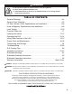
DANGER a) Do not store a spare LP cylinder under or near this appliance. b) Never fill the cylinder beyond 80% full. c) If the information in (a) and (b) is not followed exactly, a fire causing death or serious injury may occur. TABLE OF CONTENTS: General Warnings . . . . . . . . . . . . . . . . . . . . . . . . . . . . . . . . . . . . . . . . . . . . 3-4 General Fryer Warnings . . . . . . . . . . . . . . . . . . . . . . . . . . . . . . . . . . . . . . . .
GENERAL WARNINGS: WARNING 3 • Leak test all connections before first use, even if grill was purchased fully assembled and after each tank refill/exchange. Check the propane tank rubber seal for damage. • Always check the grill and propane tank prior to each use as indicated in the “Checking for Leaks” & “Pre-Start Check List” sections of this manual. • Never use natural gas in a unit designed for liquid propane gas. • Never use charcoal, lava rocks or wood briquets in a gas grill.
• Maintain a minimum clearance of 36 inches (91 cm) between all sides of grill, deck railings, walls or other combustible material. Not adhering to these clearances may prevent proper ventilation and can increase the risk of a fire and/or property damage, which could also result in personal injury. DO NOT use grill under overhead unprotected combustible construction. • DO NOT use or install this grill in or on a recreational vehicle and/or boat.
• In the event of rain, snow, hail, sleet or other forms of precipitation while cooking with oil/grease, cover the cooking vessel immediately and turn off the appliance burner and gas supply. Do not attempt to move the appliance or cooking vessel. • Fryer/boilers shall not be used on or under any apartment or condominium balcony or deck. • When cooking, the fryer/boiler must be on a level, stable, noncombustible surface in an area clear of combustible material.
LP GAS CYLINDER (TANK) SPECIFICATIONS AND INSTALLATION: WARNING • ONLY connect this grill to a Type 1 cylinder valve. The Type 1 valve can be identified with the large external threads on the valve outlet. • DO NOT connect to a propane cylinder exceeding a 20 lb. (9.1 kg) capacity. • DO NOT connect to a cylinder that uses any other type of valve connection device. • Inspect the propane tank valve rubber seal for cracks, wear or deterioration prior to use.
LP GAS CYLINDER (TANK) SPECIFICATIONS: LP gas cylinder (not supplied with this grill) The LP (Liquid Propane) gas cylinder specifically designed to be used with this grill must be 12” (30.5 cm) diameter x 18” (45.7 cm) tall and have a 20 lb. (9.1 kg) capacity incorporating a Type 1 cylinder valve and an over-filling protection device (OPD). This grill is designed to fit Worthington, Manchester or SMPC brand 20 lb. (9.1 kg) cylinders.
LP GAS CYLINDER (TANK) RUBBER SEAL INSPECTION: • Inspect the propane tank valve rubber seal for cracks, wear or deterioration prior to use. A damaged rubber seal can cause a gas leak, possibly resulting in an explosion, fire or severe bodily harm. • Inspection should be done each time the propane tank is connected to the grill, has been refilled, exchanged or has not been used for more than 60 days. • Do not use a propane tank with a damaged rubber seal.
HOSE AND REGULATOR: Your grill is equipped with a Type 1 connection device with the following features: 1. The system will not allow gas flow from the cylinder until a positive connection to the valve has been made. Note: The cylinder valve and all grill burner knobs must be turned OFF before any connection is made or removed. 2. A regulator flow limiting device, when activated, restricts the flow of gas to 10 cubic feet per hour.
DANGER To prevent fire or explosion hazard: • DO NOT smoke or permit ignition sources in the area while conducting a leak test. • Perform test OUTDOORS in a well ventilated area that is protected from the wind. • Never perform a leak test with a match or open flame. • Never perform a leak test while the grill is in use or while grill is still hot. WHEN TO PERFORM A LEAK TEST: • • • • After assembling your grill and before lighting for the first time, even if purchased fully assembled.
PRE-START CHECK LIST: DANGER Property damage, bodily harm, severe burns, and death could result from failure to follow these safety steps. These steps should be performed after the grill has been assembled and prior to each use. DO NOT operate this grill until you have read and understand ALL of the warnings and instructions in this manual. • Ensure that the grill is properly assembled. • Inspect the gas supply hose for burns, chaffing, kinks, and proper routing before each use.
MATCH LIGHTING THE MAIN BURNERS: Lighting Hole 1. Open lid before lighting. 2. Turn the burner control knobs to “OFF”. 3. Place a paper match in the end of the matchlighter. Strike the match and place through lighting hole in the left hand side of the grill to approximately 1/2” (1 to 2 cm) from the burner. 4. Turn on the FAR LEFT burner control knob to the “HIGH” position. The burner should light within 5 seconds. 5.
OPERATING THE GRILL: WARNING • • • • • • • Read and follow all warnings and instructions contained in the preceding sections of this manual. Never use charcoal, lava rocks or wood briquets in a gas grill. Flavoring chips must be contained in a metal smoking box to contain ash and prevent fires. DO NOT cover cooking grates or other components with aluminum foil, as this blocks ventilation and damage to grill or personal injury may occur. DO NOT leave your grill unattended while “ON” or in use.
ROTISSERIE COOKING: • • • Your grill was pre-drilled from factory to include mounting holes for a rotisserie. Do not use a rotisserie not specifically manufactured for this grill. Read and follow all instructions provided with the rotisserie. Save instructions for future reference. Do not use the fryer burner when using a rotisserie.
THE FRYER BURNER: • • The fryer burner can be used to prepare side dishes such as beans, potatoes, corn, or to warm sauces. The fryer burner valve can be adjusted from high to low depending upon your cooking demands. HOW TO DETERMINE PROPER AMOUNT OF OIL: (For Use With Cooking Vessels That Do not Have Maximum Fill Line). Never use a cooking vessel larger than 7 quarts or one that does not fit within the opening of the fryer burner. Never use a cooking vessel larger than 10 1/2” diameter. 1.
PROPER CARE & MAINTENANCE: WARNING: If a bristle brush is used to clean any of the cooking surfaces, ensure no loose bristles remain on the cooking surfaces prior to grilling as loose bristles may attach to food. CLEANING INTERIOR OF GRILL: • We recommend cleaning off food residue immediately after cooking by gently scrubbing grates with wire bristle brush and then turning burners to “HIGH” for approximately 5 minutes. WARNING: DO NOT leave grill unattended when grill is on.
BURNER ASSEMBLY/MAINTENANCE: • Although your burners are constructed of stainless steel, they may corrode as a result of the extreme heat and acids from cooking foods. Regularly inspect the burners for cracks, abnormal holes, and other signs of corrosion damage. If found, replace the burner. • DO NOT block ventilation areas in sides, back or cart compartment of grill. Burner tubes can become blocked by spiders and other insects building their nests.
BURNER ADJUSTMENT: WARNING • DO NOT attempt to adjust burner air shutter until grill has cooled down for approximately 30 minutes. Failure to do so could cause severe burns. • Normal flame should be soft blue with yellow tips between 1 in. - 2 in. when burner is on “HIGH”. Depending on elevation, burner air shutter may need to be adjusted to obtain correct air to fuel ratio.
TROUBLE SHOOTING: To see trouble shooting or assembly videos, visit us at: Problem Possible Cause Prevention/Cure Burner will not light LP gas tank valve is closed Make sure regulator is securely attached to the LP gas tank, turn LP gas tank valve to “OPEN” LP gas tank is low or empty Check if LP gas tank is empty. If empty, replace or refill. LP gas leak 1. Turn LP gas tank valve to “CLOSED” 2. Wait 5 minutes for gas to clear 3.
Problem Possible Cause Prevention/Cure Flame blows out High or gusting winds Do not use grill in high winds Low on LP gas Replace or refill LP gas tank Burner holes may be obstructed Refer to “Burner Assembly/Maintenance” instructions Flow limiting device tripped Refer to “Regulator Resetting Procedure” Grease buildup Clean all grill parts per “Proper Care and Maintenance” instructions Excess fat in meat Trim fat from meat before grilling Excessive cooking temperature Adjust (lower) cooking
ASSEMBLY INSTRUCTIONS: READ ALL SAFETY WARNINGS & ASSEMBLY INSTRUCTIONS CAREFULLY BEFORE ASSEMBLING OR OPERATING YOUR GRILL. Make sure you have all items listed under PARTS LIST and PARTS BAG CONTENTS before you begin the installation process. Your Parts Bag will include: Qty.
WE RECOMMEND TWO PEOPLE WORK TOGETHER WHEN ASSEMBLING THIS UNIT.
1 3 4 2 7 5 6 9 8 11 10 14 12 13 17 18 16 15 20 19 21 22 23 24 25 30 29 27 36 34 26 28 35 31 32 33 FOR GRILL REPLACEMENT PARTS, COVERS & ACCESSORIES, PLEASE VISIT US ONLINE AT (Proof of purchase will be required.) Inspect contents of the box to ensure all parts are included and undamaged.
Non Locking Swivel Caster Non Swivel Caster Locking Swivel Caster Non Swivel Locking Caster Choose a good, cleared assembly area and get a friend to help you put your grill together. Lay cardboard down to protect grill finish and assembly area. CAUTION: Some parts may have Front sharp edges. Wear protective gloves if necessary. Step 1 Attach casters to the bottom of cart base using eight M6 X 12 mm bolts (black) and eight M6 star washers (black) as illustrated.
Step 6 Align tank holder brace to tank needle assembly using hinge and cotter pin as illustrated. Step 7 Right Side Cart Panel Lock the casters. Align key holes in bottom of side cart panels with corresponding pre-installed bolts. Insert key holes over bolts and slide toward back of base. Secure using two M6 X 12 mm bolts (black) as illustrated. Tighten down all bolts. Step 8 Use eight pre-installed M6 X 12 mm bolts (black) to attach the cart corner brackets to the cart base and the cart side panels.
Step 10 Use four M6 X 12 mm bolts (black) to attach the tank block bars to the cart base and the upper cart brace. Tank Block Bar Left Door Assembly Right Door Assembly Step 11 To attach door by inserting the pins in the bottom of the door into the cart base. Then, align the hole at the top of the door with the hole in the upper cart brace and insert one door hinge pin through both holes. Repeat for other door.
Step 13 Insert the three pre-attached bolts of the left side table front panel into the three keyholes of the left side table, slide downward and tighten the bolts securely. Step 14 Insert the three pre-attached bolts of the fryer assembly front panel into the three keyholes of the fryer assembly, slide downward and tighten the bolts securely.
Step 15 Attach left side table to left side of cart frame assembly. Place table over pre-attached bolts and slide toward back of grill, then tighten securely. Fasten side table front panel to grill body with one M6 X 12 mm bolt (black). Bolt Step 16 Attach right fryer burner assembly to right side of cart frame assembly. Place table over pre-attached bolts and slide toward back of grill, then tighten securely. Fasten fryer burner assembly front panel to grill body with one M6 X 12 mm bolt (black).
Step 17 Attach fryer lid to fryer assembly using two fryer hinge pins and fryer hinge cotter pins as illustrated. Figure 1 Side Fryer Step 18 Install the side fryer (Figure 1). Attach one M4 X 10 mm bolt (silver) from the top of the side fryer to secure in place (Figure 2). Attach two M4 washers and one M4 nut and one wing nut to secure the side fryer (Figure 3).
Step 19 Insert the pre-attached screws in the fryer burner valve assembly through the holes in the fryer burner front panel, then firmly seat the valve nozzle into the burner venturi. Slide the fryer burner valve assembly down in the keyholes on the fryer burner control knob bezel as shown to lock in place. Tighten with screwdriver. Install fryer burner control knob onto valve stem Step 20 Attach fryer burner igniter lead to electrode on bottom of fryer burner.
Step 21 Line up handle with bolt holes on basket and insert three M5 X 10 mm bolts (silver), three M5 star washers (silver) and three M5 nuts (silver) inside as illustrated then tighten securely. Step 22 Place the fryer burner grate onto the fryer burner table. Clip thermometer to basket and place in fryer pot onto fryer burner grate. Step 23 Slide the grease tray onto the tracks located behind and underneath the grill body assembly. Step 24 Hang grease cup from the grease tray.
Warming Rack Step 25 Sear Burner Cooking Grill Cooking Grates Place the heat distribution plates and stainless steel sear burner heat distribution plate on lower level of grill body assembly directly above burners. Heat Distribution Plates Step 26 Place cooking grills and sear burner cooking grill on support ribs directly above heat distribution plates. Step 27 Insert warming rack onto brackets so it sits above the cooking grills.
Brinkmann® 6 Burner Gas Grill (Assembled) 33
ROTISSERIE WARNINGS: WARNING ELECTRICAL GROUNDING INSTRUCTIONS: This appliance (rotisserie motor) is equipped with a three-prong (grounding) plug for your protection against electrical shock hazard. It should be plugged directly into a properly grounded three-prong receptacle. DO NOT cut or remove the grounding prong from this plug. • Always check the grill prior to each use as indicated in the “Pre-Start Check List” section of the Owner’s Manual. • Keep children and pets away.
ROTISSERIE ASSEMBLY INSTRUCTIONS: Step 1 Open grill hood and remove cooking grills. Step 2 Attach rotisserie bracket A on the left hand side of the grill using two M6 x 10 mm bolts (black) and two M6 nuts. Step 3 Slide rotisserie motor onto the rotisserie bracket A. Step 4 Attach rotisserie bracket B inside the right hand side of the grill using two M6 x 10 mm bolts (black) and M6 nuts. Step 5 Slide rotisserie forks onto spit rod. Insert spit rod into rotisserie motor.
ROTISSERIE OPERATING INSTRUCTIONS: WARNING ELECTRICAL GROUNDING INSTRUCTIONS: This appliance (rotisserie motor) is equipped with a three-prong (grounding) plug for your protection against electrical shock hazard. It should be plugged directly into a properly grounded three-prong receptacle. DO NOT cut or remove the grounding prong from this plug. OPERATING THE ROTISSERIE: 1. Install the rotisserie motor onto the motor mount bracket. 2. Ensure that the rotisserie motor is turned to “OFF.
IMPORTANTES ADVERTENCIAS DE SEGURIDAD ES NUESTRO DESEO QUE ARME Y UTILICE SU PARRILLA EN LA FORMA MÁS SEGURA POSIBLE. EL PROPÓSITO DE ESTE SÍMBOLO DE ALERTA DE SEGURIDAD ES QUE USTED PRESTE ATENCIÓN A LOS POSIBLES PELIGROS CUANDO ARME Y UTILICE SU PARRILLA. ¡CUÁNDO VEA ESTE SÍMBOLO DE ALERTA DE SEGURIDAD ATENCIÓN A LA INFORMACIÓN A CONTINUACIÓN! PRESTE ESPECIAL LEA DETENIDAMENTE TODAS LAS ADVERTENCIAS DE SEGURIDAD E INSTRUCCIONES ANTES DE ARMAR Y USAR LA PARRILLA. PELIGRO SI HUELE GAS: 1.
PELIGRO a) NO guarde un cilindro de gas de propano líquido de reserva debajo o cerca de este artefacto. b) Nunca llene el cilindro más de 80%. c) Si la información en (a) y (b) no se sigue exactamente, se puede producir un incendio y causar lesiones o hasta la muerte. TABLA DE CONTENIDOS: Advertencias Generales . . . . . . . . . . . . . . . . . . . . . . . . . . . . . . . . . . . . . . 39-40 Advertencias Generales de la Freidora . . . . . . . . . . . . . . . . . . . . . . . . . .
ADVERTENCIAS GENERALES: ADVERTENCIA • • • • • • • • • • • • • • • • • • • • • • • • • • 39 Antes de usar la parrilla por primera vez, pruebe todas las conexiones en busca de fugas, incluso si compró la parrilla totalmente armada y cada vez que vuelva a cargar el tanque. Inspeccione el sello de caucho del tanque de propano en busca de daños.
• • • • Cacerola de agua siempre debe ser utilizado cuando se fuma. No permita que el líquido en la bandeja de agua se evapore completamente. Comprobar el agua cada 2 horas y agregar agua si el nivel es bajo (un sonido chisporroteante puede indicar la necesidad de agua). Siga las instrucciones de la sección “Adición de agua” de este manual. Nunca mueva el ahumador cuando está en uso o cuando la bandeja de agua contenga líquidos calientes. Cuando la parrilla se usa, está caliente.
• • • Evite golpear o impactar contra el artefacto para evitar salpicaduras o derrames de líquidos de cocción calientes. Tenga cuidado cuando camine o se pare cerca de la freidora, ya que el aceite derramado puede haber creado una superficie resbaladiza. Nunca deje caer alimentos ni accesorios dentro del líquido de cocción caliente. Baje los alimentos y accesorios con cuidado dentro del líquido de cocción para evitar salpicaduras o desbordamientos.
ESPECIFICACIONES DEL CILINDRO (TANQUE) DE GAS LP: Cilindro de gas LP (no suministrado con esta parrilla) El cilindro de gas LP (propano líquido) específicamente diseñado para usarse con esta parrilla debe tener 12” (30.5 cm) de diámetro × 18” (45.7 cm) de alto y una capacidad de 20 lb (9.1 kg), con una válvula del cilindro Tipo 1 y un dispositivo de protección contra sobrecarga (OPD). Esta parrilla está diseñada para usarse con cilindros de 20 lb (9.1 kg) de marca Worthington, Manchester o SMPC.
INSPECCIÓN DEL SELLO DE CAUCHO DEL CILINDRO (TANQUE) DE GAS LP: • Antes de usar, inspeccione el sello de caucho de la válvula del tanque de propano en busca de fisuras, desgaste o signos de deterioro. Un sello de caucho dañado puede causar una fuga de gas, lo que posiblemente derive en una explosión, un incendio o lesiones corporales graves.
REGULADOR Y MANGUERA: La parrilla viene equipada con un dispositivo de conexión Tipo 1 con las siguientes características: 1. El sistema no permitirá la circulación de gas desde el cilindro hasta que se establezca una conexión positiva a la válvula. Nota: La válvula del cilindro y todas las perillas de los quemadores de la parrilla deben estar cerradas antes de realizar o quitar cualquier conexión. 2.
PELIGRO Para prevenir los peligros vinculados con los incendios o explosiones: • NO fume ni permita que haya fuentes de ignición en la zona donde lleve a cabo una prueba de detección de fugas. • Realice la prueba en un área bien ventilada AL AIRE LIBRE, protegida contra el viento. • Nunca lleve a cabo una prueba de detección de fugas con un fósforo o una llama. • Nunca lleve a cabo una prueba de detección de fugas con la parrilla en uso o aún caliente.
LISTA DE COMPROBACIÓN PREVIA AL ARRANQUE: PELIGRO Si no se siguen estos pasos, pueden ocurrir daños a la propiedad, lesiones corporales, quemaduras graves y la muerte. Estos pasos deben llevarse a cabo después de que la parrilla se armó y antes de cada uso. NO use esta parrilla hasta haber leído y entendido TODAS las advertencias y las instrucciones incluidas en este manual. • • • • • • • Asegúrese de que la parrilla esté correctamente armada.
7. Para apagar, gire cada perilla de control en sentido horario hasta que se trabe en la posición “APAGADO”. Esto no apaga el flujo de gas del cilindro. Nota: Si el quemador no se enciende o la llama es muy baja, consulte la sección “Solución de Problemas” del manual del propietario. ENCENDIDO DE LOS QUEMADORES PRINCIPALES CON FÓSFOROS: Agujero de Encendido 1. Abra la tapa antes de encender. 2. Gire las perillas de control de quemadores a posición “APAGADO”. 3.
Nota: Observe la altura de la llama una vez encendida: La llama debe ser de color azul/amarillo y debe ser de 1” a 2” cuando el quemador está en la posición “ALTO”. Consulte la sección del manual sobre el ajuste de los quemadores para regular la llama. FUNCIONAMIENTO DE LA PARRILLA: ADVERTENCIA • • • • • • • Lea y siga todas las advertencias y las instrucciones incluidas en las secciones anteriores de este manual. Nunca use carbón, rocas volcánicas o briquetas de madera en una parrilla a gas.
PARA MINIMIZAR LAS LLAMARADAS: • • • • Quítele el exceso de grasa a la carne antes de cocinarla. Cocine carnes con alto contenido de grasa (pollo o cerdo) con una llama baja o indirectamente. Asegúrese de que la parrilla esté sobre una superficie nivelada y de que la grasa pueda escurrirse por la parrilla a través del orificio de drenaje en la parte inferior hasta el depósito o la batea para la grasa. Limpie la parrilla con frecuencia para minimizar la acumulación de grasa.
USO DE OTRAS FUNCIONES DE LA PARRILLA: ADVERTENCIA • • • • • • Lea las instrucciones de encendido de la parrilla para encender el quemador de la freidora. Nunca cierre la cubierta del quemador de la freidora cuando el quemador esté encendido. Utilice una olla de 26,7 cm (10 1/2”) o más pequeña que entre en la apertura del quemador de la freidora fácilmente. Centre la olla en el quemador. Nunca coloque más de 6,8 kg. (15 libras) sobre el quemador de la freidora.
CÓMO DETERMINAR LA CANTIDAD ADECUADA DE ACEITE: (Para usar con recipientes de cocción que no tienen línea máxima de llenado). Nunca utilice un recipiente de cocción más grande que 7 cuartos o uno que no entre en la apertura del quemador de la freidora. Nunca utilice un recipiente de cocción de más de 26,7 cm (10 1/2”) de diámetro. 1. Coloque el producto alimenticio en el soporte. (cesta del filtro) 2. Coloque el producto alimenticio y el soporte en el recipiente vacío. 3.
CUIDADO Y MANTENIMIENTO ADECUADOS: ADVERTENCIA: Si usa un cepillo de cerdas para limpiar cualquiera de las superficies para cocinar, asegúrese de que no queden cerdas sueltas sobre dichas superficies antes de usar la parrilla, ya que las cerdas sueltas se pueden pegar a la comida.
LIMPIEZA Y MANTENIMIENTO DE LOS QUEMADORES: • Mantenga el artefacto libre de materiales combustibles, gasolina, y otros líquidos y vapores inflamables. • Mantenga las aberturas de ventilación del gabinete del cilindro despejadas y libres de desechos. • Inspeccione visualmente las llamas de los quemadores para corroborar su correcto funcionamiento (vea el gráfico ilustrativo en el apartado “Conjunto de los Quemadores/Mantenimiento” de la sección “Cuidado y Mantenimiento Adecuados”).
AJUSTE DE LOS QUEMADORES: ADVERTENCIA • NO intente ajustar el obturador de aire de los quemadores hasta que la parrilla se haya enfriado durante aproximadamente 30 minutos. Si no cumple con esta indicación, puede sufrir quemaduras graves. • Las llamas normales deben ser de color azul claro con puntas amarillas, y deben ser de entre 1” y 2” cuando el quemador está en la posición “ALTO”.
SOLUCIÓN DE PROBLEMAS: Para ver videos de montaje o solución de problemas, visítenos en: Problema Causa posible Prevención/Cuidado El quemador no enciende La válvula del tanque de gas LP está cerrada Cerciórese de que el regulador esté conectado al tanque de gas LP con firmeza; gire la válvula del tanque de gas LP a la posición “ABIERTA” El nivel del tanque de gas LP es bajo o el tanque está vacío Verifique si el tanque de gas LP está vacío.
Problema Causa posible Prevención/Cuidado La llama es amarilla o anaranjada Es posible que el quemador nuevo contenga aceites residuales de la fabricación Encienda la parrilla durante 15 minutos en la posición “ALTO” con la tapa cerrada Es posible que haya telarañas o nidos de insectos en los tubos venturi de los quemadores.
SUGERENCIAS PARA COCINAR CON LA PARRILLA: HIGIENE: • • • • Siempre lávese las manos minuciosamente con jabón y agua caliente antes de manipular la comida y después de manipular carne vacuna o de pollo cruda, o mariscos/pescados.
INSTRUCCIONES DE ARMADO: LEA DETENIDAMENTE TODAS LAS ADVERTENCIAS DE SEGURIDAD E INSTRUCCIONES ANTES DE ARMAR Y USAR LA PARRILLA Verifique que tiene todos los artículos indicados en la LISTA DE PARTES y en el CONTENIDO DE LA BOLSA DE PARTES antes de comenzar con el proceso de instalación. La bolsa de partes incluirá lo siguiente: Cant.
RECOMENDAMOS QUE ESTA UNIDAD SEA ARMADA POR DOS PERSONAS Se necesitan las siguientes herramientas para armar esta Parrilla a Gas Brinkmann® Select con 6 Quemadores: • Destornillador de Cabeza Phillips • Llave de Tuercas Hexagonales LISTA DE PARTES: 1 1 Rejilla para Calentar 2 1 Rejilla para Dorar 3 2 Rejillas Grandes para Cocinar 4 1 Rejilla Pequeña para Cocinar 5 1 Placa de Distribución de Calor del Quemadora para dorar 6 5 Placas de Distribución de Calor 7 1 Tapa de la Freidora 8 1 Cuerpo de la Parrilla
1 3 4 2 7 5 6 9 8 11 10 14 12 13 17 18 16 15 20 19 21 22 23 24 25 30 29 27 36 34 26 28 35 31 32 33 PARA ENCONTRAR PARTES DE REEMPLAZO PARA SU PARRILLA, CUBIERTAS Y ACCESORIOS, FAVOR DE VISITARNOS AL (La prueba de compra se requiere.) Inspeccione el contenido de la caja para verificar que todas las partes estén incluidas e intactas.
Elija un lugar adecuado y despejado para armar la parrilla y pídale a un amigo que le ayude. Tienda cartón sobre el suelo para proteger el acabado de la parrilla y el área de armado. Ruedilla Giratoria Non Locking que No Traba Swivel Caster Ruedilla No Non Swivel Giratoria Caster Locking Ruedilla Swivel Caster Giratoria que Traba Ruedilla Non No Swivel Giratoria queCaster Traba Locking CUIDADO: Algunas partes pueden tener bordes afilados. Póngase guantes de protección si es necesario.
Paso 6 Alinear el soporte del sostenedor del tanque al montaje de la aguja del tanque utilizando bisagra y chaveta, como se ilustra. Paso 7 Panel Lateral Derecho del Carro Panel Lateral Izquirda del Carro Bloquee las ruedas. Alinear los agujeros de clave en fondo del lado carrito paneles con sus correspondientes pernos preinstalados. Inserte agujeros clave sobre los pernos y deslice hacia la parte posterior de la base. Sujete con dos pernos de M6 X 12 mm (negro) como se ilustra. Apriete todos los pernos.
Paso 10 Use cuatro pernos M6 X 12 mm (negros) para fijar la barra del bloque del tanque a la base del carro y el apoyo superior del carro. Barra del Bloque del Tanque Paso 11 Para fijar las puertas al montaje del carro, inserte el pasador de la puerta inferior en el orificio de la base. Luego, alinee el orificio en la parte superior de la puerta con el agujero en el abrazadera superior del carro e inserte un perno de la bisagra de la puerta a través de ambos agujeros. Repita para el otro lado.
Paso 13 Inserte los tres pernos de preadjunta del panel delantero de la mesa lateral izquierda en los tres orificios de la tabla del lado izquierdo, deslice hacia abajo y apriete los pernos. Paso 14 Inserte los tres pernos de preadjunta del panel frontal montaje freidora en los tres orificios de la asamblea freidora, deslice hacia abajo y apriete los pernos.
Paso 15 Fije la mesa lateral izquierda al lateral izquierdo del montaje del armazón del carro. Coloque la mesa sobre los pernos previamente fijados y deslícela hacia la parte trasera de la parrilla; luego ajuste los pernos firmemente. Ajuste el panel frontal de la mesa lateral al cuerpo de la parrilla con un perno M6 X 12 mm (negro). Perno Paso 16 Fije el montaje del freidora lateral derecho al lateral derecho del montaje del armazón del carro.
Paso 17 Coloque la tapa del freidora al montaje de la freidora usando dos pasadores de la bisagra de la freidora y chavetas como se ilustra. Figura 1 Quemador Freidora Paso 18 Instale la freidora lateral (Figura 1). Conecte un M4 X 10 mm perno (plata) de la parte superior de la freidora lateral para asegurar en su lugar (Figura 2). Ponga las dos arandelas M4 y una tuerca M4 y una tuerca de ala para asegurar el quemador lateral (Figura 3).
Paso 19 Inserte los tornillos preanexados en el ensamble de la válvula del quemador freidora a través de los orificios del panel frontal del quemador freidora, luego firmemente asiente la boquilla de la válvula dentro del venturi del quemador. Deslice el montaje de la válvula del quemador hacia abajo en los orificios del bisel de la perilla del control del quemador freidora como se muestra para asegurarlo en su lugar. Ajuste con el destornillador.
Paso 21 Alinee el mango con los orificios para pernos en la cesta e inserte tres pernos M5 X 10 mm (plateado) y tuercas M5 (plateado) como se ilustra; luego ajuste con firmeza. Paso 22 Coloque la rejilla de la quemador freidora sobre la mesa de la quemador freidora. Clip termómetro a la cesta y colocar la olla en la rejilla del quemador freidora. Paso 23 Deslice la bandeja para grasa sobre los rieles que se encuentran detrás y debajo del montaje del cuerpo de la parrilla.
Rejilla para Calentar Paso 25 Coloque las placas de distribución de calor y la placa de distribución de calor de acero inoxidable del quemador para dorar en el nivel inferior del montaje del cuerpo de la parrilla, directamente sobre los quemadores. Paso 26 Rejilla para Dorar Rejillas para Cocinar Placas de Distribución Coloque las parrillas de cocción y la parrilla de cocción del quemador para dorar en las barras de soporte, directamente sobre las placas de distribución de calor.
Parrilla Brinkmann® de 6 Quemadores a Gas (Armada) 70
ADVERTENCIAS DEL ASADOR: ADVERTENCIA INSTRUCCIONES PARA CONECTAR A TIERRA LOS ARTEFACTOS ELÉCTRICOS: Este artefacto (motor del asador estilo rotisserie) está equipado con un enchufe de tres clavijas (de puesta a tierra) para proteger al usuario contra el electrochoque. Este enchufe debe conectarse directamente a un receptáculo para tres clavijas conectado correctamente a tierra. No corte ni quite la clavija de puesta a tierra del enchufe.
INSTRUCCIONES DE ARMADO DEL ASADOR: Paso 1 Abra la cubierta de la parrilla y quite las rejillas para cocinar. Paso 2 Instale el soporte A del asador en el lado izquierdo de la parrilla con dos pernos M6 x 10 mm (negros) y dos tuercas M6. Paso 3 Deslice el motor del asador en el soporte A del asador. Paso 4 Coloque el soporte B del asador dentro de la parte derecha de la parrilla con dos M6 x 10 mm pernos (negros) y dos tuercas M6. Paso 5 Deslice las horquillas del asador en la varilla.
INSTRUCCIONES DE FUNCIONAMIENTO DEL ASADOR: ADVERTENCIA INSTRUCCIONES PARA CONECTAR A TIERRA LOS ARTEFACTOS ELÉCTRICOS: Este artefacto (motor del asador estilo rotisserie) está equipado con un enchufe de tres clavijas (de puesta a tierra) para proteger al usuario contra el electrochoque. Este enchufe debe conectarse directamente a un receptáculo para tres clavijas conectado correctamente a tierra. No corte ni quite la clavija de puesta a tierra del enchufe. FUNCIONAMIENTO DEL ASADOR ESTILO ROTISSERIE: 1.
FOR COVERS, ACCESSORIES AND OTHER PRODUCTS, PLEASE VISIT US ONLINE AT: PARA CUBIERTAS, ACCESORIOS Y OTROS PRODUCTOS, FAVOR DE VISITARNOS POR LA RED MUNDIAL EN: WARRANTY The Brinkmann Corporation warrants to the original purchaser that the Brinkmann® 6 Burner Gas Grill is free from defects due to workmanship or materials for: Lifetime: on stainless steel tube burners Five-year: on all other stainless steel parts Three-year: on valves, frame, housing, cart, igniter, cooking grates and other related parts The