
Installation Guide


HANDLESET INSTALLATION INSTRUCTIONS
DOOR PREPARATION - READ THIS FIRST!
B
B
e
e
f
f
o
o
r
r
e
e
i
i
n
n
s
s
t
t
a
a
l
l
l
l
i
i
n
n
g
g
y
y
o
o
u
u
r
r
n
n
e
e
w
w
B
B
r
r
i
i
n
n
k
k
s
s
H
H
a
a
n
n
d
d
l
l
e
e
s
s
e
e
t
t
,
,
p
p
l
l
e
e
a
a
s
s
e
e
r
r
e
e
f
f
e
e
r
r
t
t
o
o
t
t
h
h
e
e
s
s
e
e
p
p
a
a
r
r
a
a
t
t
e
e
D
D
o
o
o
o
r
r
P
P
r
r
e
e
p
p
a
a
r
r
a
a
t
t
i
i
o
o
n
n
I
I
n
n
s
s
t
t
r
r
u
u
c
c
t
t
i
i
o
o
n
n
s
s
.
.
P
P
r
r
o
o
c
c
e
e
e
e
d
d
w
w
i
i
t
t
h
h
t
t
h
h
e
e
i
i
n
n
s
s
t
t
r
r
u
u
c
c
t
t
i
i
o
o
n
n
s
s
b
b
e
e
l
l
o
o
w
w
o
o
n
n
l
l
y
y
a
a
f
f
t
t
e
e
r
r
y
y
o
o
u
u
h
h
a
a
v
v
e
e
c
c
o
o
n
n
f
f
i
i
r
r
m
m
e
e
d
d
t
t
h
h
a
a
t
t
y
y
o
o
u
u
r
r
d
d
o
o
o
o
r
r
h
h
a
a
s
s
b
b
e
e
e
e
n
n
p
p
r
r
o
o
p
p
e
e
r
r
l
l
y
y
p
p
r
r
e
e
p
p
a
a
r
r
e
e
d
d
.
.
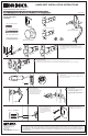
Included Hardware for
Handleset Deadbolt
Installation
S
1
3
/4" (19mm)
• Q
ty 2
S2 1-1/2" (38mm) • Qty 3
S3 1-1/2" (38mm) • Qty 2
Select the appropriate latch based on the door backset.
T
he backset is the distance from door edge to center of hole on the door
f
ace. Included are two latches, one for a 2-3/8” (60mm) backset and
another longer latch for a 2-3/4” (70mm) backset. Select the appropriate
l
atch for your door.
S
elect the desired faceplate.
a
) Determine appropriate faceplate design (square or rounded corners) to match faceplate cutout in the door.
b) If desired faceplate is not already on latch, remove existing faceplate by separating faceplate from latch and “snap” on desired faceplate.
Install the Latch.
a
) Insert latch into side hole of door making sure that beveled face of latch is
t
owards door jamb.
b) Using two 3/4” (19mm) Wood/Machine thread screws (
S1) assemble latch
t
o door. Tighten screws firmly.
Install the Interior Knob.
a) Position interior knob onto square drive spindle
so that screw holes are aligned with screw
posts on either side of spindle.
b) Insert and tighten two 1-1/2” (38mm) long
machine screws (
S2) through the rosette of the
knob.
Install the Outside Handleset
a) Insert square drive spindle of the
handleset through square crank in latch.
b) Align screw post at bottom of handle
with pre-drilled 5/16” (8mm) hole.
c) Push handleset flush against door.
Complete the Handleset Installation.
a) Insert the 1-1/2” (38mm) long
machine screw (
S2) through beveled
washer (bubble towards door) into
the internally threaded post at the
bottom of handleset. T
ighten firmly
.
b) Snap on decorative screw cover onto
beveled washer.
Install the Handleset Strike Plate.
a) Install strike plate using two 1-1/2"
(38mm) wood screws (
S3) and tighten
firmly.
I
nterior Knob
(
Style varies with Series Number)
S
crew Cover Beveled Washer
Screw Cover Beveled Washer
H
andleset Strike Plate
H
andleset
(Style varies with Series Number)
(S3)
(S2)
(S2)
(S2)
Rosette
(S3)
1
2
3
4
5
6 7
2-3/8” Backset
L
atch
2-3/4” Backset
L
atch
H
andleset Latch (2-3/4” Backset)
H
andleset Latch (2-3/8” Backset)
P
atent Pending
Hampton Products International Corp.
50 Icon
Foothill Ranch, CA 92610-3000
www.hamptonproducts.com
1-800-562-5625
Made in China
©
2007 Hampton Products International Corp.
999-00123 REV
A
4/07
(S1)
a
b
LIFETIME WARRANTY - FINISH & MECHANICAL
This product is fully warranted to be free of defects in material and workmanship for the life of the product. If a defect in material or workmanship occurs, call
800–562–5625 for instructions on how to have it replaced or repaired free of charge. This warranty is null and void if the lock was used for purposes for which it
was not designed. NOT LIABLE FOR INCIDENTAL, INDIRECT, OR CONSEQUENTIAL DAMAGES. Some states do not allow the exclusion or limitation of incidental or
consequential damages, so the above limitation or exclusion may not apply to you. This warranty gives you specific rights, and you may also have other rights that
vary from state to state.