OWNER'S MANUAL A E R ATO R S P R E A D E R MO DE L : AS-30 BH AS-40 BH Assembly Installation Operation Repair Parts For use with Lawn/Garden Tractors For the latest product updates and setup tips: Visit us on the web! www.brinly.com Important: This manual contains information for the safety of persons and property. Read it carefully before assembly and operation of the equipment! L-1711BH Rev. D L-1711-BH.
CONGRATULATIONS on your new Brinly-Hardy Lawn Aerator. It has been designed, engineered, and manufactured to give you the best possible dependability and performance. Keep all nuts, bolts and screws tight to be sure the equipment is in safe working condition. The vehicle and attachment should be stopped and inspected for damage after striking a foreign object. The damage should be repaired before restarting and operating the equipment.
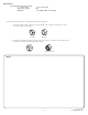
REFERENCE Tools Required for Assembly: * ½" wrench (2) * Pair work gloves * Hammer * 3/4" wrench (2) OR * 10" Adjustable wrench (2) A note about nuts used in the assembly of your Aerator Spreader: 1. Jam Nuts and Hex Nuts spin freely on the bolt threads. Usually a lock washer is used to lock the nut securely in place. Jam Nut Hex Nut 2. Lock Nuts and Nylon Lock Nuts provide resistence after several turns on the bolt threads. A wrench is normally required during installation.
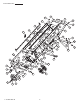
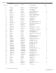
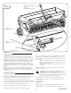
Parts Reference 37 13 7 2 30 8 1 1 3 46 39 43 52 34 37 35 48 16 26 19 22 41 42 45 41 5 29 47 47 47 4. L-1711BH L-1711-BH.-3 Rev.
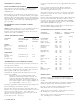
Parts List AS-302 REF. NO. 1 *2 *3 4 5 6 7 8 9 10 11 12 *13 14 15 16 17 18 19 20 21 22 23 *24 25 26 27 28 *29 30 *31 *32 33 *34 35 36 *37 38 39 *40 *41 *42 43 *44 *45 *46 *47 48 49 *50 *51 52 53 54 55 56 57 58 * Parts AS-402 DESCRIPTION PART NO.
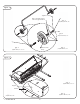
Figure 1. Tighten securely Nut to be tight against tube not against wheel. Qty. 4 (41)Hex Jam Nut, 1/2" Qty. 2 (45)Lock Washer, 1/2" Wheel to turn freely. Qty. 2 (32)Hex Bolt, 1/2" x 3-1/2" Qty. 6 (47)Flat Washer, 1/2" Figure 2. Qty. 4 (34)Hex Bolt, 5/16" x 2" Hopper Towbars Qty. 4 Qty. 4 (44)Lock Washer, 5/16" (40)Hex Nut, 5/16" 6. L-1711BH L-1711-BH.-3 Rev.
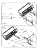
Figure 3. Qty. 2 (37)Hex Bolt, 5/16" x 3" Qty. 2 Qty. 2 (40)Hex Nut, 5/16" (44)Lock Washer, 5/16" Qty. 1 Towbars (50)Drawbar Pin 1/2" x 2-1/2" Qty. 1 (51)Hairpin Cotter (NOT TO SCALE) Figure 4. Qty. 2 (46)Flat Washer, 5 /16" Qty. 2 (31)Hex Bolt, 5/16" x 3/4" Hopper Transport Plate Qty. 2 (40)Hex Nut, 5/16" Qty. 2 (44)Lock Washer, 5/16" 7 7. L-1711-BH.-3 L-1711BH Rev.
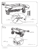
Figure 5. Towbars Qty. 2 (13)Cap Tube Qty. 2 (37)Hex Bolt, 5/16" x 3" Qty. 2 (2)Hex Lock Nut, 5/16" Do not over tighten nut, Wheel Support must pivot. Wheel Support Figure 6. Install Grip (not shown) Wheel Support Lift Handle Qty. 2 (40)Hex Nut, 5/1 Qty. 2 (42)Carriage Bolt, 5/16" x 1-3/4" Qty. 2 (44)Lock Washer, 5/16" 8. L-1711-BH.-3 L-1711BH Rev.
Make sure Lever points forward. Install Grip (not shown) Figure 7. Qty. 1 (31)Hex Bolt, 5/16" x 3/4" Qty. 1 (44)Lock Washer, 5/16" Qty. 1 (40)Hex Nut, 5/16" OPERATION WHEN TO USE: Your Aerator-Spreader should not be used when lawn conditions are too wet or too dry. This can be determined by digging a small amount of soil (about three inches deep) and checking it. If soil appears powdery and brittle- its too dry. Wait until a later date, after a rainfall.
OPERATION Continued... Set the spreader flow control at the approximate flow control setting. FLOW CONTROL ADJUSTMENT Place 5 pounds of material in the Hopper. Weigh the material before and after spreading 100 square feet to determine amount of material used. Open and Close: The material flow is shut off by moving Control Lever to the left and locking into "V" notch on calibration plate. Move unit to measure area, lower aerator tines, open Flow Control Lever. Drive the 40 ft.
Limited Warranty B r i n l y - H a r d y C o m p a n y wa r r a n ts o n ly to th e o r ig in al retai l purchaser that thi s product w i l l remai n free of defects i n w o r k m a n s h i p a nd m a te r ia ls u n d e r n o r m a l u se a n d servi ce for a peri od of tw o (2) years (N OTE : ni nety (90) days for c o m m e r c i a l o r r e n ta l u se ) co m m e n cin g with th e d ate of purchase.
INTENTIONALLY LEFT BLANK L-1711BH Rev.
OWNER’S MANUAL OWNER’S MANUEL DUMANUAL PROPRIÉTAIRE MANUEL DEL DU PROPRIÉTAIRE MANUAL PROPIETARIO MANUAL DEL PROPIETARIO AERATOR SPREADER / AÉRATEUR-ÉPANDEUR / AIREADOR-ESPARCIDOR AERATOR SPREADER / AÉRATEUR-ÉPANDEUR / AIREADOR-ESPARCIDOR MODEL: Assemblage Montaje Assembly MODÈLE : MODEL: Assemblage Montaje Assembly Installation Instalación Installation MODELO: MODÈLE : Installation Instalación Installation MODELO: Mode d’emploi Operación AS - 3 0 BH Operation Modede d’emploi Operación Operation Pièces répa
FÉLICITATIONS pour votre nouvel aérateur de pelouse Brinly-Hardy. Il a été conçu, usiné et fabriqué pour vous offrir la meilleure fiabilité et la meilleure performance possibles. Si vous avez des problèmes que vous ne pouvez pas corriger facilement, n’hésitez pas à contacter notre service à la clientèle bien informé au numéro sans frais suivant : 1-877-728-8224. Nous comptons des techniciens compétents, bien formés pour vous aider à réparer votre aérateur. • • • Veuillez lire et conserver ce manuel.
RÉFÉRENCE Outils requis pour l’assemblage : * clé * clé de 3/4 po (2) * paire de gants de travail OU * marteau * clé réglable de 10 po (2) Une note au sujet des écrous utilisés dans l’assemblage de votre aérateur-épandeur : 1. Les contre-écrous et les écrous hex tournent librement sur les filets des boulons. Normalement, une rondelle frein est utilisée pour verrouiller l’écrou bien en place. Contre-écrou Écrou hex 2.
Référence aux pièces 37 13 7 2 30 8 1 1 3 46 39 43 52 34 37 35 48 16 26 19 22 41 42 45 41 5 29 47 47 47 28 L-1711BH-FR Rev. D 4.
Liste de pièces AS-302 N° RÉF.
Figure 1. Resserrez bien L’écrou doit être serré contre le tube et non contre la roue Qté 4 (41) contre-écrou hex., 1/2 po Qté 2 (45) rondelle frein, 1/2 po Qté 2 La roue doit tourner librement (32) boulon hex, 1/2 po x 3 1/2 po Qté 6 (47) rondelle plate, 1/2 po Figure 2. Qté 4 (34) boulon hex., 5/16 po x 2 po Trémie Trémie Qté 4 Qté 4 (44) rondelle frein, 5/16 po (40) écrou hex., 5/16 po 6. L-1711BH-FR L-1711BH Rev.
Figure 3. Qté 2 (37) boulon hex., 5/16 po x 3 po Qté 2 (40) écrou hex., 5/16 po Qté 2 (44) rondelle frein, 5/16 po Qté 1 Trémie (50) goupille de la barre d’attelage 1/2 po x 2 1/2 po Qté 1 (51) goupille en épingle à cheveux (N’EST PAS À L'ÉCHELLE) Figure 4. Qté 2 (46) rondelle plate, 5/16 po Qté 2 (31) boulon hex., 5/16 po x 3/4 po Trémie Plaque de transport Qté 2 (40) écrou hex., 5/16 po Qté 2 (44) rondelle frein, 5/16 po L-1711BH-FR 19 L-1711BH Rev. D 7.
Figure 5. Barres de remorquage Qté 2 (13) tube embout Qté 2 (37) boulon hex., 5/16 po x 3 po Qté 2 (2)Contre-écrou, 5/16 po Ne resserrez pas trop l'écrou, le support de roue doit pivoter. Support de roue Figure 6. Installez la prise (non illustrée) Support de roue Soulevez la poignée Qté 2 (40)écrou hex, 5/16 po Qté 2 (42) boulon de carrosserie, 5/16 po x 1 3/4 po Qté 2 (44)contre-écrou hex., 5/16 po 8. L-1711BH-FR L-1711BH Rev.
Assurez-vous que le levier soit vers l’avant Installez la prise (non illustrée) Figure 7. Qté 1 (40)écrou hex., 5/16 po Qté 1 (31)Boulon hex 5/16 po x 3/4 po Levier supérieur Position de transport Qté 1 Levier inférieur (44) rondelle frein, 5/16 po MODE D’EMPLOI : QUAND L’UTILISER : Votre aérateur-épandeur ne devrait pas être utilisé lorsque la pelouse est trop humide ou trop sèche.
Placez 5 libres de matière dans la trémie. Pesez la matière avant et après l’étalement de 100 pieds carrés pour déterminer la quantité de matière utilisée. MODE D’EMPLOI suite... RÉGLAGE DE COMMANDE DE DÉBIT________________ Déplacez l’unité pour l’aire à mesurer, abaissez les dents de l’aérateur, ouvrez le levier de commande de débit. Conduisez sur le parcours de 40 pieds, arrêtez l’unité et fermez le levier de commande de débit.
Garantie limitée Brinly-Hardy garantit seulement à l’acheteur original au détail que ce produit sera libre de défauts de fabrication et de matériaux sous une utilisation et un service normaux pendant une période de deux (2) ans (NOTE : quatre-vingt-dix (90) jours pour une utilisation commerciale) à partir de la date d’achat. Toutes les pièces qui s’avèrent défectueuses pendant la période de garantie seront remplacées, avec une preuve de date d’achat, aux frais de la société Brinly-Hardy.
INTENTIONALLY LEFT BLANK L-1711BH Rev.
OWNER’S MANUAL OWNER’S MANUEL DU MANUAL PROPRIÉTAIRE MANUELDEL DU PROPRIÉTAIRE MANUAL PROPIETARIO MANUAL DEL PROPIETARIO AERATOR SPREADER / AÉRATEUR-ÉPANDEUR / AIREADOR-ESPARCIDOR AERATOR SPREADER / AIREADOR-ESPARCIDOR MODEL: Assemblage Montaje Assembly/ AÉRATEUR-ÉPANDEUR MODÈLE : MODEL: MODELO: MODÈLE : MODELO: AS - 3 0 BH A -S4-030BH BH AS A S - 40 BH Installation Assembly Operation Installation Repair Parts Operation ForRepair use with Lawn/Garden Parts Tractors For use with Lawn/Garden Tractors Inst
FELICIDADES por la compra de su nuevo aireador-esparcidor Brinly-Hardy para césped. Esta unidad ha sido diseñada, planeada y manufacturada para brindarle la mejor confiabilidad y el mejor rendimiento posibles. Mantenga apretados todos los tornillos, tuercas y pernos para asegurarse de que el equipo esté en condiciones de trabajo seguras. En caso de golpear contra algún objeto externo, detenga el vehículo y el accesorio e inspecciónelos para comprobar que no estén dañados.
REFERENCIA Herramientas requeridas para el montaje: * Llave de 1/2 pulg. (2) * Un par de guantes de trabajo * Martillo * Llave de 3/4 pulg. (2) O BIEN * Llave ajustable de 10 pulg. (2) Observaciones sobre las tuercas utilizadas en el montaje de su aireador-esparcidor: 1. Las contratuercas y las tuercas hexagonales giran libremente en las roscas de los pernos. Generalmente, para trabar una tuerca firmemente en posición se utiliza una arandela de seguridad. Contratuerca Tuerca hexagonal 2.
Referencia de piezas 37 13 7 2 8 1 23 44 46 39 17 34 43 35 52 16 26 41 42 45 41 5 29 47 47 32 48 19 22 47 Rev. D L-1711BH-SP 4.
Lista de piezas AS-302 REF. N.° 1 *2 *3 4 5 6 7 8 9 10 11 12 *13 14 15 16 17 18 19 20 21 22 23 *24 25 26 27 28 *29 30 *31 *32 33 *34 35 36 *37 38 39 *40 *41 *42 43 *44 *45 *46 *47 48 49 *50 *51 52 53 54 55 56 57 58 AS-402 PIEZA N.
Figura 1. Ajuste firmemente La tuerca debe apoyar firmemente contra el tubo y no contra la rueda. Cant. 4 (41) Contratuerca hexagonal de 1/2 pulg. Cant. 2 (45) Arandela de seguridad de 1/2 pulg. La rueda debe girar libremente. Cant. 2 (32) Perno hexagonal de 1/2 pulg. x 3-1/2 pulg. Cant. 6 (47) Arandela plana de 1/2 pulg. Figura 2. Cant. 4 (34) Perno hexagonal de 5/16 pulg. x 2 pulg. Tolva Barras de remolque Cant. 4 Cant. 4 (44) Arandela de seguridad de 5/16 pulg.
Figura 3. Cant. 2 (37) Perno hexagonal de 5/16 pulg. x 3 pulg. Cant. 2 (40) Tuerca hexagonal de 5/16 pulg. Cant. 2 (44) Arandela de seguridad de 5/16 pulg. Cant. 1 (50) Pasador de barra de remolque de 1/2 pulg. x 2-1/2 pulg. Barras de remolque Cant. 1 (51) Chaveta de horquilla (NO SE MUESTRA A ESCALA) Figura 4. Cant. 2 (46) Arandela plana de 5/16 pulg. Cant. 2 (31) Perno hexagonal de 5/16 pulg. x 3/4 pulg. Tolva Placa de transporte Cant. 2 (40) Tuerca hexagonal de 5/16 pulg. Cant.
Figura 5. Barras de remolque Cant. 2 (13) Tapa de tubo Cant. 2 (37) Perno hexagonal de 5/16 pulg. x 3 pulg. Cant. 2 (2) Tuerca de seguridad hexagonal de 5/16 pulg. No ajuste excesivamente la tuerca, pues el soporte de las ruedas debe pivotar. Soporte de ruedas Figura 6. Instale la agarradera (no se muestra) Soporte de ruedas Manija de elevación Cant. 2 (40) Tuerca hexagonal de 5/16 pulg. Cant. 2 (42) Perno de cabeza redonda de 5/16 pulg. x 1-3/4 pulg. Cant.
Asegúrese de que la palanca quede hacia adelante. Instale la agarradera (no se muestra) Figura 7. Cant. 1 (40) Tuerca hexagonal de 5/16 pulg. Cant. 1 (31) Perno hexagonal de 5/16 pulg. x 3/4 pulg. Palan ca su p er io r Posición de transporte Cant. 1 Palanca inferior (44) Arandela de seguridad de 5/16” pulg. OPERACIÓN CUÁNDO USAR: Desarme todos los terrones de material a medida que llene la tolva.
OPERACIÓN (continuación) AJUSTE DEL CONTROL DE FLUJO una distancia de 30 pies en el jardín, que es la necesaria para cubrir 100 pies cuadrados (3.33 pies [40 pulg.] x 30 pies = 100 pies2). Apertura y cierre: El flujo de material se interrumpe desplazando la palanca de control hacia la izquierda y trabándola en la muesca en V de la placa de calibración. Ajuste el control de flujo del aireador-esparcidor al valor más aproximado al número obtenido.
Garantía limitada Brinly-Hardy Company garantiza sólo al comprador minorista original que este producto se mantendrá libre de defectos de mano de obra y materiales en condiciones de uso y servicio normales por un período de dos (2) años (NOTA: noventa (90) días para uso comercial o de alquiler) a partir de la fecha de compra.
L-1711BH Rev.