
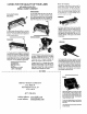
Product Manual


Refer
to
Fig. 3
• Determine
your
requirements
for
Disk
Angling
and
Spacing. (Refer
to
Fig. 6 &
7)
Disk
Gang
Angles are
adjustable
for
10, 15, & 20
degree
Angles. The 15 de-
gree
position
(center of the
Adjusting
Slot
in Disk
Hanger)
is
recommended
to start. The 10 and 20
de-
gree Angles 'are for less aggressive or
more
aggressive
Disking
Action.
(I
Attach
each
completed
Disk Gang Assembly
to
the
Tray as
shown
into
inner sets of
slots
in Tray using
3/8
11
x
ill
Carriage
Bolts,
3/8"
Flat
Washers'(next
to
slots
in;Disk
Hangers),
3/8
11
Lock Washers and
3j8
U
nuts. The
cutting
edges
of
Disk Blades face
toward
outside
of
Disk Tray.
NOTE: The carriage
bolts
must
be inserted
from
the
TOP J
locking
in the selected Disk Gang Angle -
(15!
Center of
Adjusting
Slot to
start).'
• Normal
operation
of
the
Disk is at the 15
degree
Disk Gang Angle with
the
two
center
Disk
Blades as
close
together
as possible. This is
accomplished
by
placing
the
Carriage Bolts in
the
CENTER
and
inner slots of
the
Tray and
movinq
as close
to
the
center
of
the
Tray as
possible.
• Tighten all fasteners
previously
assembled and
Lubricate (Grease) both Disk Gangs through the Grease
Fittings
until
grease
comes
out
around ends of disk
hanger.
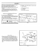
Assembly as Rear (Tandem) Disk Harrow
(Requires purchase of additional Disk Harrow).
Refer to Fig'. 4
• Assemble both Disk Gangs as
described
in Fig. 1.
• Assemble Hitch Bar,
Adaptor
Coupler
and Tray
as
described
in Fig. 2.
•
Determine
your
requirements
for
disk
angling. Disk
Gang Angles are
adjustable
for
10, 15 & 20
degree
angles. The 15
degree
position
(Center of the Adjust-
ing
Slot
in Disk
Hanger)
is
recommended
to
start.
The 10 & 20
degree
angles are
for
less aggressive or
more aggressive
disking
action.
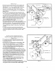
•
Attach
each
completed
Disk Gang Assembly
to
the
Tray as shown,
into
the
OUTER
set
of
slots
in
Tray,
using
3/8"
x
tCarrlaqe
80Its,3/8
11
Flat
Washers(next
to
slots
in
Disk Hanqers),
3/8
u
Lock Washers and
3/8"
Hex Nuts.
Cuttlnq
edges
of
Disk Blades
face
toward
center
of
Disk Tray
to
throw
dirt
in
(opposite
of
the
Front Disk
Harrow Blades). Inner Blades
of
Disk Gangs to be set
apart 8
u
-1
OU
(See Fig. 7).
NOTE: The carriage bolts
must
be inserted from the
TOP, locking in the selected Disk
Gang
Angle -
(15='
Center
of
Adlustinq
Slot
to
start).
• Tighten all fasteners previously assembled and
Lubricate (Grease)both Disk
G.angs
through GreaseFittings
until grease comes
out
around ends
of
Disk Hanger.
5
Hex Nut,
3/8
11
Fig. 3
Fig.4
Flat Washer,
3/8
11
Lock Washer I
3/8"