
Instructions / Assembly


1009725-A
12.
67
17
38
22
69
38
40
40
22
69
17
ASSEMBLY
================================================================================================
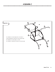
Using the hardware in Panel 10, assemble one 3/8” Nut
(17) on each end of the Hamper Stop Rod (67) until it is
approximately in the center of the threads.
67 17
Assemble each end of the Hamper Stop Rod (67) through
the holes on the front of the Upper Side Tubes (38) and
Lower Side Tubes (69).
Using the remaining hardware in Panel 10, assemble one
3/8” Lock Nut (22) on each end of Hamper Stop Rod (67).
Tighten the Lock Nut (22) until Hamper Stop Rod (67) is fl ush
with the top of the Lock Nut (22).
Note: Hold the Hamper Stop Rod (67) with Pliers while
tightening the Lock Nuts (22).
Upper and Lower Side Tubes should be trapped between
the Nut (17) and Lock Nut (22) on the Hamper Stop Rod (67)
but still loose enough to pivot freely. If the tubes do not pivot
freely, loosen Nut (17).
Pull up on bottom of Hamper (40) from “J” Channel and hook
”J” Channel onto Hamper Stop Rod (67).
Snap side fl aps to Hamper (40) bottom as shown. Note: Flap
should be on the outside of Lower Side Tubes (69) after
assembly.
Figure 09
Hook
Snap
Snap
“J” Channel
70
66
38
69
38
67
Figure 10
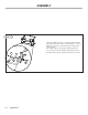
Locate and align the holes in the upper rear tube (53)
with the side tubes (38). Locate and align the holes
in the lower rear tube (66) with the bottom tube (69).
Stand in the bottom of the hamper. Insert the end of
the spring rod (70) into the lower holes aligned in the
previous step. Pull up on the upper rear tube (66)
and insert the other end of the spring rod (70) into
the upper holes.
Please note that this step must be done with eye
protection (safety glasses) and gloves as the spring
rod requires some force to install. After installation
the spring rod will be slightly bent.