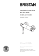
Installation Instructions and User Guide Artisan Thermostatic Surface Mounted Bar Shower Valves Models covered: AR2 SHXVOFF, AR2 SHXMTFF & AR2 SHXSMFF Please keep this booklet for future reference. Installer, when you have read these instructions please ensure you leave them with the user.
Contents Thank you for choosing Bristan, the UK’s leading showers and taps expert. Your Bristan shower valve is a thermostatic mixer incorporating a wax capsule thermostat to ensure constant shower temperatures. These instructions are for your guidance to a safe and successful installation and should be left with the user. All products manufactured and supplied by Bristan are safe providing they are installed correctly and receive regular maintenance in accordance with these instructions.
Important Safety Information • Please read these instructions thoroughly and retain for future use. • All products manufactured and supplied by Bristan are safe provided they are installed, used correctly and receive regular maintenance in accordance with these instructions. • If you are in any doubt about your ability to install this shower valve safely you must employ the services of an experienced qualified plumber.
General Information Operating pressure range: Minimum 0.1 bar, Maximum 5.0 bar. Maximum static pressure: 10.0 bar. This product has been tested to the TMV2 scheme which complies with the BS EN 1287:1999 (LP) and BS 1111:1999 (HP) thermostatic mixing valve standards and satisfies the requirements of the water supply (water fittings) regulations 1999 and current bylaws. BS 6700 recommends the temperature of stored water should never exceed 65°C.
Product features 1. Water Flow Control Water flow settings: Off ( ), Medium (eco ) and High ( ). 1 Controls the amount or flow of water from the showerhead. When in medium (eco ) setting the button must be pressed to increase the water flow. 2 2. Temperature Control Adjustable temperature control. Only press the button (and turn the control) when a water temperature over 38˚ is required.
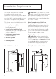
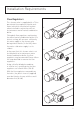
Installation Requirements This shower valve must be installed in compliance with current water regulations. If you have any doubts about the water regulation requirements contact your local water services provider or use the services of a professional plumber. Important: If you install this shower valve with a gravity fed system, there must be a minimum head (vertical distance) from the underside of the cold water storage tank to the showerhead position of at least 1 metre.
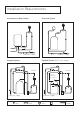
Installation Requirements Instantaneous Water Heater Unvented System cold mains supply Pumped System cold mains supply Pumped System (with Essex flange) 1m min. 1m min. If less than 1m see note.
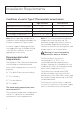
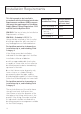
Installation Requirements Conditions of use for Type 2 (Thermostatic mixer) valves High Pressure Low Pressure 10 10 Maximum Static Pressure (Bar) Flow Pressure, Hot & Cold (Bar) 0.5 to 5 0.1 to 1 Hot Supply Temperature (˚C) 55 to 65 55 to 65 Cold Supply Temperature (˚C) Equal to or Less than 25 Equal to or Less than 25 Note: Valves operating outside these conditions cannot be guaranteed by the Scheme to operate as Type 2 valves.
Installation Requirements Flow Regulators This shower valve is supplied with a 7 litre per minute flow regulator fitted in each water inlet which must be left in place when installed in conjunction with an instantaneous water heater/combination boiler. Fitting both flow regulators and turning the water heater/combination boiler to its hottest setting, will ensure a sufficiently hot water supply to the shower valve during winter months (in the UK), when the mains cold water supply is at its coldest.
Installation Requirements This fitting needs to be installed in accordance with the following Installation Requirements and Notes (IRN) to ensure they meet the requirements of the Water Supply (Water Fittings) Regulations 1999 and the Scottish Byelaws 2004. IRN R001: See text of entry for Installation Requirements or Notes.
Dimensions (mm’s) 150 117 74 35 67 260 660 * *Note: The Riser rail wall brackets can be positioned up or down the riser rail as required. This allows any existing holes to be reused or covered by the wall brackets. The brackets can also be adjusted to sit in the middle of the tiles or in the tile joints.
Specifications Specifications Inlet connections: 15mm compression with 150mm between centres. Operating pressure range: Min. 0.1 bar - Max. 5.0 bar - Maximum recommended imbalance between hot and cold supply should not exceed a ratio of 5:1. Maximum outlet temp: Factory pre-set to 41°C (can be re-set to suit site conditions). Supply requirements: Minimum cold water supply temperature: 5°C. Maximum cold water supply temperature: 25°C. Maximum hot water supply temperature: 80°C.
Pack Contents - AR2 SHXVOFF C 1 Shower valve 1 2 Wall plates x2 3 Olives x2 4 Fixing bridges x2 2 5 Covers x2 6 6 Filter washers x2 7 Wall plate fixings x4/4 3 8 Plastic inserts x2 4 7 5 8 13
Pack Contents - AR2 SHXSMFF C 1 Shower valve 1 2 Wall plates x2 3 Olives x2 4 Fixing bridges x2 2 5 Covers x2 6 Filter washers x2 7 Wall plate fixings x4/4 3 8 Plastic inserts x2 9 Showerhead (single function) 4 10 Rubber washers x2 11 Shower hose 12 Riser rail 5 13 Riser rail fixings x4/4 6 7 8 12 10 9 13 11 14
Pack Contents - AR2 SHXMTFF C 1 Shower valve 1 2 Wall plates x2 3 Olives x2 4 Fixing bridges x2 2 5 Covers x2 6 Filter washers x2 7 Wall plate fixings x4/4 3 8 Plastic inserts x2 9 Showerhead (3 function) 4 10 Rubber washers x2 11 Shower hose 12 Riser rail 5 13 Riser rail fixings x4/4 6 7 8 12 10 9 13 11 15
Installation - First Fix Before Installation Flush through the pipework to ensure removal of debris. Turn off the mains water supply and close any isolating valves. 1. Prepare water supply pipes The centres of the hot and cold water supply pipes should be 150mm apart. At least 30mm of the 15mm diameter supply pipes should protrude through the finished wall surface. Important: Water supplies to the mixer must be with hot on the left and cold on the right when viewed from the front. 2.
Installation - Second Fix 1. Fit covers Screw the covers (5) over the wall plates/ fixing bridges (4), so they are flush against the wall. 4 5 4 5 2. Attach shower valve Place the filter washers (6) into the shower valve fixing nuts. Position the shower valve (1) against the fixing bridges and carefully tighten the shower valve fixing nuts onto the fixing bridges. Do not overtighten. Note: Take care not to damage the finish of the shower valve fixing nuts.
Installation - Riser Rail 1. Mark the position Position the assembled riser rail on the wall, bearing in mind the different heights of people likely to use the shower and the length of the hose when connected to the shower. Note: If replacing an existing riser rail, check to see if the existing holes can be reused or covered by the new wall brackets. Try to avoid drilling close to the edge of tiles, drill in the middle of the tiles or in the tile joints.
Installation - Riser Rail cont. 3.Insert rail clamps Insert the rail clamps into both wall brackets. 4. Insert riser rail Push the riser rail up through the bottom wall bracket. Push the slider down onto the riser, ensuring it is the correct way up - as shown. Then push the riser rail up through the top wall bracket. Rail clamp Bottom wall bracket 5. Tighten rail clamps Centre the riser rail within the wall brackets and tighten both clamps onto the rail. 6.
Installation - Riser Rail cont. Attaching the Shower hose 7. Connect shower hose to shower valve Screw the shower hose (ribbed nut end) onto the mixer ensuring that the rubber washer is fitted. 8. Connect shower hose to showerhead Screw the shower hose (conical end) onto the showerhead ensuring that the rubber washer is fitted. Place the showerhead into the slider.
Operation Water Flow Control (1) Water flow settings: Off ( ), Medium (eco ) and High ( ). Controls the amount or flow of water from the showerhead. 1 When in medium (eco ) setting the button must be pressed to change the setting. 2 Temperature Control (2) Adjustable temperature control. Only press the button (and turn the control) when a water temperature over 38˚ is required.
Commissioning Commissioning notes for Thermostatic Mixing Valves The first step in commissioning a thermostatic mixing valve is to check the following: 1. The designation of the thermostatic mixing valve matches the application. 2. The supply pressures are within the valves operating range. 3. The supply temperatures are within the valves operating range. 4. Isolating valves (and strainers preferred) are provided.
Maintenance General Cleaning Cartridge Maintenance Your fitting has a high quality finish and should be treated with care to preserve the visible surfaces. All surfaces will wear if not cleaned correctly, the only safe way to clean your mixer is to wipe with a soft damp cloth. Stains can be removed using washing up liquid. All bath cleaning powders and liquids will damage the surface of your fitting, even the nonscratch cleaners.
Maintenance - cont. Adjusting the Temperature The shower valve has been factory set with equal (balanced) hot and cold water supply pressures with the hot water supply at 65˚C. If your operating conditions are different from those above, the outlet water temperature may differ from the factory setting. If required the shower valve can be recalibrated to suit your own temperature requirements. Set the temperature control to 38˚C and check the temperature of the water with a thermometer.
Hard Water Regions in the UK Soft to moderately soft 0 - 100mg/l as calcium carbonate equivalent Hard to very hard Above 200mg/l as NE calcium carbonate SR equivalent DH NE SR DH CA CA DL TS NE DL LA LA Slightly hard to moderately hard 100 - 200mg/l as calcium carbonate equivalent BD FY L LL CH LL SY LD SA NP CF TA EX PL TR BB PR YO HG BD CA FY HU PR LS BB DH HG DL TS SR YO TS LS HU HX HX WF LA WF BL OL HD BL OL HD DN YODN WN HG WN L MBD M S WA S WA LN SK LN SK LL HU BB LS CH
Troubleshooting Symptom Cause Remedy No flow or low flow rate and / or varying temperatures. Check showerhead, hose and filters for any blockage. Clean as necessary, refer to Maintenance section (page 23). Partially closed stop or service valve in water supply pipework to the shower valve. Open stop or service valve. Instantaneous water heater cycles on and off as the flow rate or pressure is too low. Increase water flow rate or pressure through system.
Troubleshooting - cont. Symptom Cause Remedy Maximum water temperature too hot or cold. Maximum water temperature set incorrectly. Reset maximum water temperature. Refer to ‘Maximum Temperature Setting’ in Commissioning section (page 22) and ‘Adjusting the Temperature’ in Maintenance section (page 23). Outlet water temperature too hot / cold. Inlet filter is partially blocked. Check insert filters for any blockages and clean as necessary. Installation conditions outside operating parameters.
Guarantee Bristan offers solid guarantees to provide you with complete peace of mind. Taps and Mixers 5 year parts and 1 year labour*. Gold, painted and special finishes 3 years parts only. All subject to proof of purchase. Mixer Shower Valves 5 year parts. 5 year labour* (subject to registration), or 1 year with proof of purchase. Gold, painted and special finishes 3 years parts only. Pumps and Power Showers 2 year parts. 1 year labour* (subject to registration).
Guarantee & Service Policy • Components that are subject to general wear and tear such as filters, seals, ‘O’ rings and washers etc. • Damage caused by faulty installation • Damage caused by lime scale or any waterborne debris • Damage caused by inappropriate cleaning products (see maintenance section) • Damage caused by the use of non-Bristan parts • The product being used for a purpose other than intended by the manufacturer.
Notes Please use this space to add any notes you or your installer may have regarding the plumbing system/installation of this product.
Notes 31
Part Number: FI AR2 SHX Issue: D1 Bristan Group Ltd. Birch Coppice Business Park Dordon Tamworth Staffordshire B78 1SG Web: www.bristan.com Email: enquire@bristan.