Installation Manual & User Guide HARHDE200 FlexStar HDE-200 Embedded Exporter HARHDE200-PROFAN Profanity Delay Upgrade HARHDE200-PPM Arbitron PPM Interface Upgrade HARHDE200-PROF/PPM Combined Upgrade 75-56 Revision F • 3/12 BROADCAST COMMUNICATIONS DIVISION Support phone: 217.222.8200 • e-mail: tsupport@harris.com Internet: http://ecustomer.broadcast.harris.
ii H A R R I S C O R P O R A T I O N Revision F • 3/12
Contents 3 SOFTWARE (CONTINUED) CE Declaration of Conformity ....................... iv Hazard/Warning Label Identification ............ v 3.5 HDE-200 Configuration ........................ 3-9 Manual Revision History .............................. vi 3.5.1 File Menu ........................................ 3-9 Safety Instructions ......................................... v 3.5.2 Device Menu .................................... 3-9 Trademark Information ................................. vi 3.5.
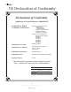
CE Declaration of Conformity Declaration of Conformity Application of Council Directive: 2004/108/EC Standards To Which Conformity Is Declared: EN55103-1:1997 (Professional Audio) EN55022 Class A Radiated Emissions Conducted Emissions EN55103-1 Magnetic Emissions EN61000-3-2 Harmonics EN61000-3-3 Voltage Flicker EN55103-2:1997 (Professional Audio) EN55103-2 Magnetic Immunity EN61000-4-2 EN61000-4-3 EN61000-4-4 EN61000-4-5 EN61000-4-6 EN61000-4-11 Manufacturer's Name: Harris Corporation Manufacturer's Ad
Hazard/Warning Label Identification C A U T I O N REFER SERVICING TO QUALIFIED SERVICE PERSONNEL ONLY. WARNING: TO REDUCE THE RISK OF FIRE OR ELECTRIC SHOCK, DO NOT EXPOSE THIS PRODUCT TO RAIN, HIGH HUMIDITY OR MOISTURE. The Exclamation Point symbol, within an equilateral triangle, alerts the user to the presence of important operating and mainte-nance (servicing) instructions in product literature and instruction manuals. WARNING: THIS PRODUCT USES A UL-LISTED 5 VDC POWER SUPPLY.
Manual Revision History Revision A - Preliminary release Revision B - First official release, numerous technical and format changes Revision B.
Product Overview T 1 of Exporters. Its Ethernet output can be set to use UDP, TCP/IP, or Starlink MAC, making it fully hanks for joining the broadcasters employ- compatible with Digital STLs, DHCP-controlled local area networks, and even the public Internet. ing Harris Corporation products.
1 Product Overview Down) select which delay (Diversity Delay or the input signal feeds this output and to set the length optional Profanity Delay) is being monitored and of the Diversity Delay to keep the analog and digi- allow basic Ramp Up/Down control. The 10-Char- tal broadcast audio outputs aligned in time. acter displays show the status of the delay. The A digital monitor output (Ref Mon Out) can feed Ramp Up/Down LEDs indicate whether the de- a local digital audio monitor.
1 Product Overview 1.2 Specifications Input Sample Rate (Main Delay In, MPS Audio In): 32 kHz to 96 kHz Output Signal Format (Ref Mon Out and Main Delay Out): 110 ohm AES Output Sample Rate (Ref Mon Out and Main Delay Out): 44.1 kHz AES Output Compliance (Ref Mon Out and Main Delay Out): 16-bit Encoded HD output: As specified by iBiquity IRSS (iBiquity Reference System Software) ver 4.x. Compliance RoHS: Fully compliant FCC: Meets FCC Part 15, under CE mark UL: N/A.
1 Product Overview 1.3 Warranty 3. Upon receipt of replacement Equipment (or a part thereof), Customer has thirty (30) days to tender the defective Equipment (or part thereof) to the return carrier for shipment to the service center designated by Harris. If Customer does not timely return the defective Equipment (or a part thereof), Harris shall invoice Customer for the list price of such Equipment (or part thereof), plus applicable shipping.
1 Product Overview Customer ’s abuse, mishandling, misuse, negligence, improper storage, servicing or operation, or unauthorized attempts to repair or alter the Equipment in any way. Customer must provide qualified technical personnel to maintain and repair the Equipment. Warranty, Harris will re-perform the applicable Services at Harris’ expense.
1 Product Overview or Licensed Program that (A) has been altered or modified, except by Harris; (B) has not been installed, operated, repaired, or maintained in accordance with instructions supplied by Harris; (C) has been subjected to abnormal physical or electrical stress, misuse, negligence, or accident; or (D) is used in ultrahazardous activities.
2 Hardware T 2.1.1 AUDIO CONNECTIONS he HDE-200 can be mounted in a studio, There are four AES-3 balanced digital audio connections using XLR-type connectors. All con- terminal room, or transmitter facility. It requires one form to standard AES-3 (AES/EBU) digital wiring practices (3 volt signals, 110 ohm, balanced rack unit (1RU) of space. No special venting require- lines) and levels (-20 dBFS corresponds to 0 VU on the on-screen metering).
2 Hardware Installation an undelayed analog broadcast signal. The Diver- 2.0 host port; a Remote Logic I-O connector; a sity Delay is set using the ECC app. GPS antenna input; and clock outputs used when an HD Radio Importer and HD Radio Exciter are The fourth digital audio connection is a Reference Monitor output (Ref Mon Out) that can feed co-located with the HDE-200. a pair of local digital monitor speakers.
2 Hardware Installation NOTE: The HDE-200 uses two IP ramp times and allows profanity delays of up to addresses, one for the CPU (default: 35 seconds to be set through the ECC app. This 10.10.10.10), the other for the iBiq- delay is completely separate from—and does not uity HD Radio DSP board (default: affect, the Diversity Delay built into the HDE-200. 10.10.10.22).
2 Hardware Installation panel display board, as shown on the previous For signal shielding, connect the digital audio page. Replace the top cover, then rack mount the cable shields at both the HDE-200 and the inter- HDE-200 using four rack screws.
2 Hardware Installation 2.3.3 AUDIO CONNECTIONS HD Radio Exciter is remotely located, a 10 MHz GPS reference at the Exciter is strongly recom- All audio wiring to/from the HDE-200 is AES/ mended. EBU digital (AES-3). Each audio connector (3-pin, XLR-type) uses this pinout: Under some conditions a GPS reference at the Exciter may not be essential. Exporter Reference AES/EBU Digital Inputs & Outputs mode is used for this implementation.
2 Hardware Installation the Fostex 6301D. It can alternately be used as a All digital outputs (Main Delay Out, Ref Mon source for a balanced AES-3, 44.1 kHz master Out, the HD Radio data stream and the two Post sample clock signal. Delay Loop outputs) use a 44.1 kHz sample rate Pins 2 and 3 of each digital input and output that is time-synchronized using the GPS System are fully protected against static (ESD), overvolt- clock signals.
2 Hardware Installation REMOTE I/O LOGIC CONNECTOR using transformers, because of inher- 1 15 ent protocol differences between the 30 AES-3 and S/PDIF formats. Rane 16 Pin numbers on the chassis connector Corp. has a well-written application PIN 1 3 5 7 9 11 16 17 18 19 20 22 23 24 25 26 27 31 33 35 39 41 note (www.rane.com/note149.html) which addresses AES/EBU and S/PDIF signal interfacing.
Diversity Delay Ramp Up (-) 22 20 Critical Fault Tally 35 Ballpark Delay Tally Diversity Delay Ramp Down (-) 23 Profanity Delay Enable (+) 9 Profanity Delay Ramp Up (-) 24 5 Other Tally Common 16 Ramp Up Tally, Diversity HDE-200 Internal Logic 17 Ramp Down Tally, Diversity Profanity Delay Ramp Down (-) 25 Profanity Delay Dump (-) 39 Other Enable (+) 11 Other Tallies 7 31 Ramp Complete Tally, Diversity Diversity Delay Tallies Diversity Delay Enable (+) 1 Diversity Delay Tally Common 18 R
2 Hardware Installation 10 MHz REFERENCE IN 1PSS IN HDX-FM Exciter Connections, Detailing the 10 MHz Connection The HD Radio main channel audio, part of the HD Radio data stream sent out of the Exporter’s Ethernet ports, must be sent to and received by the HD Radio Exciter. The Exporter Link port is Using a Studio Remote Panel with the HDE-200 specifically designed to receive the E2X data stream from the Exporter when using TCP or UDP.
2 Hardware Installation MAIN AES ANALOG L/ MONO ANALOG R/ AUX AES SCA AUDIO GND pin 1 #1 pins 2,3 #2 pins 4, 5 AUDIO INPUTS FM Analog Broadcast Input on an HDX-FM Exciter HDE-200 Network and USB Connections 2.3.
3 Software T he HDE-200 does not need to be networked If security is enabled in the ECC app, there are five security levels that allow varying levels of ac- with an admin computer during normal operation, cess and control over the ECC app and any networked HDE-200 Exporters. but a WinXP (SP2 or later),Vista (Business or Ulti- Four User Groups are added to the Windows operating system when the ECC app is installed.
3 Control Center Software A No Credentials user is anyone who logs into set up and use these User Groups when the ECC a computer with the ECC app but is not a mem- app is being run under the control of the engi- ber of any ECC User Group. If they open the ECC neering staff on a secure administration PC. app the standard HDE-200 monitor screen can Again, these User Groups are not activated in be viewed.
3 Control Center Software 3.2 Installing the ECC App one using the app on that computer. Use Ev- The ECC app is supplied on a USB 2.0 flash eryone when multiple users will log into the computer and need to access ECC. drive (Harris p/n 7320514000-1), along with other administration apps and PDF files. 4. The illustrations used in the following instruc- Continue the installation by clicking Next on the Select Installation Folder screen and tion show WinXP screens.
3 Control Center Software 1. To add or remove users from an HDE-200 Groups window. Type in the new users’ Win- user group, right click on the My dows login names in the Enter the object Computer icon and select Manage. names to select dialog box. To enter multiple names, separate each name with a semicolon (;). For example, if you want to add both John Doe, who logs in as jdoe, and Phil Smith, who logs in as psmith02, then type in: jdoe;psmith02. 2.
3 Control Center Software name is valid, the displayed name will auto- Alternately, use the Windows Programs menu matically update to append the local com- to start the ECC app: Start > Programs > Harris puter Corp > FlexStar > HDE-200 Control Center. name to the username (LOCAL_COMPUTER\ jcommissioner). f) Click OK to close the Properties window. Main Window, with no HDE-200 Selected To remove a user, open up the properties window for that group.
3 Control Center Software 3.4 Editing the HDE-200 Network Settings The Exporter Browser Window shows all of the Harris HDE-200s it has detected on the local network. To select a device double-click on its name To edit the network settings for a new HDE- (or click to highlight its entry, then click OK, or 200 using the “direct” method, install the ECC app press Enter on the keyboard) to select that HDE- onto a laptop or desk computer with the IP ad- 200 and close the window. dress of 10.10.10.2.
3 Control Center Software 2. Move the USB flash drive from the HDE200 to a USB port on the computer running the ECC app. Wait a moment for the USB Step 5 flash drive to be recognized by Windows. 3. Click System > Address Configuration Util- ity to open the Configuration Window. Step 3 Step 6 Step 4 4. Click Load Config from USB... to open a File HDE-200 Configuration Window Selection window. Navigate to the folder with the new HDE-200’s config file (e.g., E:\HDE200\00-50-C2-0E-0D-30). Click 5.
3 Control Center Software Exciter Link Configuration Details Use one of three HDE-200 transmission modes: 1. Unicast (to connect to one Flexstar Exciter using a local network or a bidirectional TCP/IP-capable STL, e.g. an Intraplex STL HD or Moseley Starlink 9003T1) - Enter the Flexstar Exciter’s Exporter Link IP address (e.g., 10.10.10.11) as the Exciter Address. - Select port 11000 and UDP protocol. Contact Harris field service if there is a compelling reason to use TCP.
3 Control Center Software Backing up the New Configuration Files When the direct connection method is used to update the HDE-200 files, follow steps 1 and 2 in order to write a MAC address-named folder from the updated HDE-200 to the USB flash drive. Use Windows Explorer to then backup that folder to the admin computer.
3 Control Center Software NOTE: Always confirm which HDE200 the ECC app is connected to— especially when there are multiple HDE-200 Exporters in the network, before editing any settings. 3.5.
3 Control Center Software audio sample is 1/44,100 of a second or 22.7 mi- is the maximum ramp time. The actual ramp time croseconds). may be much shorter, especially with spoken word programming. Adjusting the delay time can be done by doubleclicking the Absolute Diversity Delay time (which Diversity Correction then turns blue) and entering a new delay time.
3 Control Center Software 3.5.4 PROFANITY MENU too weak to be received properly. When Enable Blend is checked, the receiver blends from the HD Radio signal back to the analog broadcast signal. The Enable Blend setting affects how the HD Radio receivers operate, which means that it also affects how much Diversity Delay is required to align the analog broadcast with the HD Radio sig- Profanity Menu Items nal.
3 Control Center Software Delay Management Section The Total Profanity Duration and the Dump Duration are displayed in seconds.milliseconds.There is some interaction between the two controls since adjusting the Total Profanity Duration can affect the Dump Duration since the maximum Dump Duration is equal to the setting of the Total Pro- Profanity Duration Slider Bar fanity Duration. The settings can be changed using one of these up window, click on any other part of the methods: 1. computer screen.
3 Control Center Software 3.5.5 SYSTEM MENU Station ID The lower section of this window is where the entries used by the Station Information Service Transport Data (SIS Data) are entered. Note that the current HDE-200 firmware release is in compliance with NRSC document SY_IDD_1020s, Rev F. The Country Code is entered into the Country Code entry box. At this writing, there is little utility in selecting anything other than US in this box.
3 Control Center Software 3.5.5.2 Station Information Service in the first payload of a block leaving the second payload of that block empty. Click System > Station Information Service... to open the SIS data schedule window. Ten SIS There are a few arcane restrictions regarding messages are available for scheduling, as shown the placement of payloads beyond the above de- in the following illustration. scription. Fortunately, the ECC software disciplines these restrictions for you.
3 Control Center Software 3.5.5.3 Other Controls Messages needing more than two payloads to complete will be repeated slower than the 1.5 second frame rate, unless they are scheduled to appear more than once per frame. For example if the Slogan Standard uses all 56 characters, it will need 16 payloads to complete. If it’s scheduled four times per frame, it takes about six seconds for a full display on the HD Radio receiver’s display: 16 / 4 (payloads/times per frame) X 1.
3 Control Center Software Ramp Mode Select Main Only when the Main AES input provides the signal for both the analog and the This setting affects how the HDE-200 Diver- HD Radio modulation paths. The AES Fault indi- sity and optional Profanity Delay ramping algo- cation is suppressed since the MPS input will not rithms operate. There are three ramp modes on have a valid AES signal.
3 Control Center Software while there is program material level above a certain threshold; a remarkably fast 20% ramp rate is then used when the program material level falls below this threshold. This has the effect of deviously shortening or lengthening gaps between spoken words. The advantage of Smart Ramp is that listeners cannot discern a change of pitch. At the same time, the duration that the ramp remains in process is dramatically reduced.
3 Control Center Software munity Announce IP address and port. Normally If you hover your mouse over the different ele- the Multicast address and port are left set to their ments of the available devices on the dialog box, a default settings, but these may be edited for spe- pop-up dialog box appears describing the item. This Signal Chain dialog box is expected to be- cial purposes.
3 Control Center Software North American Time Zone Settings HDE-200 firmware can be downloaded from Newfoundland (-210) Central ( -360) the Harris Broadcast Customer Portal. See page Atlantic (-240) Mountain (-420) 5-8 for access information. Eastern (-300) Pacific (-480) Note that various firmware files will be found on the site under: Download Software Updates > Enable Regional DST is checked for Regions Radio Transmission > HD FM > HDE-200 Ex- or Nations that observe DST.
3 Control Center Software 3.5.5.8 Preferences low the USB flash drive to be recognized by Windows. 7. Click System > Preferences... to open the HDE- 200 Control Center Preferences pop-up window Click Install. In the pop-up window, select which shows which IP address the computer is the USB flash drive as the destination.
3 Control Center Software Windows Users and Groups to control access to to the Internet, to check for updates, use a com- the ECC app features. You must log into the ECC puter connected to the Internet and navigate to: app, using your User Credentials as an Engineer http://support.broadcast.harris.com/ Using the Harris Customer Portal requires reg- or Commissioner, to then make any new changes istration. If you already are registered, enter your on the HDE-200 configuration. username and password.
Using the HDE-200 T he HDE-200 has limited front panel con- 4 lect, Headphone Volume up and Headphone Volume Down, are needed to quickly select, view, and trols, which are for engineering use only. Board op- listen to any input or output. A dual row dot matrix display shows the name erators and other users interface with the HDE-200 of the Monitor Source Signal in its top row while the stereo signal level is shown in the lower row.
4 Using the HDE-200 going to the three Ethernet ports, thus monitor- lay is ramping: an up arrow indicates the delay is ing of this signal can only be done at the HD building or getting longer and a down arrow indi- Radio Exciter. cates the delay is ramping out or getting shorter. Pressing the Down or Up ( 4.1.2 HEADPHONE VOLUME ADJUST Pressing the HP Volume Down or Up ( ) button that has a lit LED has no action, whereas pressing the button with the unlit LED reverses the ramp ) direction.
4 Using the HDE-200 4.2 Using the ECC App To start the ECC app, double-click Any user can monitor any HDE-200 through its icon on the desktop. A program the Exporter Control Center software (ECC app) shortcut is also added to the Windows running on a studio computer. Any HDE-200 Ex- Programs menu. Click Start > Programs > Harris porter in the network can be monitored, or moni- Corp > FlexStar > HDE-200 Control Center. tored and controlled, depending upon the credentials of the logged in user.
4 Using the HDE-200 Name of the active HDE-200 Menu Items Analog Broadcast Audio Signal Level Meter Source Selectors (Pre or Post Delay) Diversity Delay Status & Ramp Controls HD Radio Audio Signal level HDE-200 Status Indicators ECC App, Main Window 4.2.
4 Using the HDE-200 Meter Source Selection Average Levels Peak Levels Diversity Delay Status Bar Ramp Down Button Ramp Up Button Diversity Status and Ramp Controls Peak Signal Alarms ECC App Meter Features ing upon the amount of signal processing). Peak the diversity delay is 0% with 0.00 seconds delay. levels are held for one second before decaying.
4 Using the HDE-200 4.2.3 PROFANITY DELAY CONTROL When the Profanity Delay is dumped, the delay When the optional Profanity Delay is active on instantly starts to rebuild the delay using the as- the HDE-200 being displayed there is a second signed ramp method so it is almost inaudible to delay status box for the Profanity Delay below the listeners. The Progress Bar will be red if the the Digital Program meter levels.
4 Using the HDE-200 GPS Lock Status Indications ARB MPS = Arbitron PPM Encoder audio for the HD Radio signal: white (PPM option not active); green (has AES clock); red (no AES clock detected) UP LOS = status of service to HD Exciter DN LOS = status of service from HD Importer UP QOS = Quality of Service to HD Exciter DN QOS = Quality of Service from HD Importer GPS = status of the GPS receiver (hovering over this indicator will pop up various messages, as shown in the illustration above, to indicate the G
5 Service T 5.1.1 PARTS ORDERING AND REPAIR INFORMATION he HDE-200 is designed to yield many years Replacement PWAs and other parts can be ob- of trouble-free 24/7 operation. But, if it does re- tained through the Harris parts department in Quincy, Illinois, USA. To ensure the correct part is quire service, read through this chapter as it pro- ordered, be sure to use the Harris product number when ordering.
5 Service 5.1.
5 Service 5.2 Technical Overview 5.1.3 UPGRADE KIT PARTS The HDE-200 consists of four PCAs: Profanity Delay (HARHDE200-PROFAN) Harris # Description or Use 21-801-1 iButton for Profanity Delay 71-1441 Installation documentation · Interface Controller Qty. 1 1 · Linux CPU · Front Panel Display · HD Radio DSP The HDE-200 block diagram is shown below.
5 Service front panel displays, and for the delay processing. put, which is sent through a tri-state octal buffer It’s programmed by the data stored in a 2 MB (U10) to J9. These signals are typically only used Flash Memory chip (U16). The board’s firmware when the HD Radio Exciter is co-located with the code can be updated, as required, by plugging a HDE-200. USB thumb drive with updated data files into the The 22.5792 MHz clock is divided by two to USB port (J6) on the rear panel.
5 Service All audio inputs and outputs conform to AES/ Refer to the Hardware chapter for a detailed EBU standards for digital signals. Each input and description of the 44-pin Remote I-O Logic con- output goes through a 110 ohm balanced AES nection. signal transformer (T2 - T9). The Main Delay In 5.2.
5 Service operational status or an error condition. These is serialized, to identify the exact codec that gen- are driven by U1, a 16-bit shift register/ latch erated the HD Radio signal. This serial number with constant current LED driver outputs. must be properly identified during HDE-200 configuration. 5.2.3 LINUX CPU The HD Radio DSP board is based on a Texas The Linux CPU is the small PCA latched into Instruments TMS320C6713 floating point DSP.
5 Service end of this boot time the Linux CPU reestablishes Check that the NIC address for the computer’s communications with the HD Radio DSP and with interface to the FlexStar network is set correctly the HD Radio Exciter. The HD Radio DSP board and verify the FlexStar Multicast settings are cor- can then begin processing the incoming audio, rect.
5 Service HDE-200 code is distributed in a compressed (.zip) folder. The code and version is listed in the folder name (e.g., HDE-200_code_1.90.5.zip). The code is downloaded from the Harris site to a computer running the ECC app. You must be logged into this computer as a Commissioner in order to access the System menu items in the ECC app. A USB Flash Drive (32MB or larger) is required to transfer new code to the Windows Firewall Exceptions List HDE-200. The program name Harris.Exporter.
5 Service 2. 3. 4. Insert the flash drive into the computer with the HDE-200 rear panel.This will automati- the .zip folder holding the updated code. cally upload the new code. The HDE-200 Start the ECC app. In the Device menu front panel shows ATTN: KEEP POWER choose Select Device and select the HDE- ON while the code is uploaded into the vari- 200 that you want to upgrade. This connects ous HDE-200 components. Once this is the computer to that HDE-200.
5 Service 7. Click Next to open the Select Installation occur, depending upon which assembly was re- Folder window. For best results, use the de- placed. fault file location. Before continuing, set the Scenario 1 1: The CPU is replaced. program access. Select Everyone so that multiple users can log into the computer and The existing DSP IP address is returned to use ECC. Continue the installation by click- the factory default (10.10.10.22). ing Next on this and the following screen.
Application Note AN10-02 Exporter Control Center and Windows 7 OVERVIEW configured as a private network. Often you can’t change The Exporter Control Center (ECC app) is supplied an unidentified network to private because that function by Harris to configure and monitor HDE-200 Exporters. is prevented by a default security setting. Thus, you have It can be run on computers using WinXP (SP2), Vista to change the security setting first so that the network is Pro, or Win7 Pro.
Application Note AN10-02 Add or Remove SnapIns and Group Policy Wizard windows window. Then click OK to close the Add or Remove window. In the MMC window’s left hand pane, there is a new entry: Local Computer Policy. Click the small arrow next 3. Verify the Windows Firewall, if on, allows the ECC app to communicate with networked HDE-200 Exporters. to the name to expand the display to show Computer You can view the Windows Firewall Permissions Configuration.