Broadcast Devices, Inc. Technical Reference Manual AES-302 Digital Audio System Two Input Digital Audio Switcher Four Output Digital Distribution System 96 KHz – 24 Bit Digital to Analog Converter Broadcast Devices, Inc. 5 Crestview Avenue Cortlandt Manor, NY 10567 Tel. (914) 737-5032 Fax. (914) 736-6916 World Wide Web: www.Broadcast-Devices.com Rev C.
Table of Contents I. Introduction 3 II. Unpacking 3 III. Installation and Connections 3 IV. Features and Operation 3 V. Initial Operations Setup Theory of Operation – Digital Switcher Error Switching Table 1. Silence Sensor Setup Table 2. Remote Control Pin out Table 3. VI. Specifications 5 5 5 6 7 VII. Warranty 8 VIII.
I. Introduction The AES-302 Digital Audio System comprises of a two input AES compatible switcher, four output digital audio DA and digital to analog converter. The unit also has status and diagnostic error indicators for troubleshooting. The AES-302 is intended for use at unattended transmitter sites or for virtually any digital switching, distribution and/or D/A conversion application.
converter providing a balanced left and right output. The unit features a front panel headphone output and volume control for easy confidence monitoring. The AES-302 can be used as a totally automatic switcher sensing loss of clock or any error displayed on the front panel to command the switcher to select the alternate feed. In addition to digital error switching, the unit features a silence sense circuit for switching upon audio failure conditions.
and remain there until the error reset is performed from the front panel or remotely. Please note that the Auto light will remain lit after an automatic switch but that the unit will perform no further switching until the error reset is performed. This feature insures that the unit will switch only once after error or loss of clock is detected and prevents the unit from “hunting” back and forth. In addition, errors and lock loss indications are held in a buffer until cleared by the error-reset button.
Silence Sensor Setup Table 2 J1/J2 in place J1 in place J2 removed J1 Removed J2 in place L+R – default Left only causes silence sensing Right only causes silence sensing Remote Control Pin out Table 3 Pin 1 Pin 2 Pin 3 Pin 4 Pin 5 Pin 6 Pin 7 Pin 8 Pin 9 +15 VDC @100mA. No Connection Select B Input Select A Input Error Reset Status Relay Common Status – “B” Selected Status - “A” Selected Ground Command input pins 3, 4, 5 require a momentary closure to ground. Status connections are to dry contacts.
VI.
VII. Warranty Broadcast Devices, Inc. products are warranted against failure due to faulty materials or workmanship for a period of one year from the date of shipment to the ultimate user. The warranty covers repair or replacement of defective parts at the factory, provided the unit has been returned prepaid by the user. All shipments to the factory shall have affixed to the outside of the container an R. A. number obtained from the factory.
VIII.
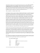
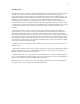
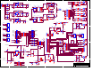
5 4 3 2 1 CR1 J1 K3 INPUT-P 6 R1 4 2 T1 1 13 3 4 4 2 1 8 Vo R11 120 1/2W CR7 C17 1N4007 .1 50V CR8 1N4007 C25 CR10 C27 1N4007 .1 50V C28 3300uF 25V 2 +15V R16 100 1/2W +5V R13 10.0K 1% MF C23 1 6 4 1 6 2 5 150uF 50V 1 2 3 4 5 6 +5V TXP4 8 2 T4 1 54R9 1/4W SILENCE U15B 1K 6 5 R17 +15V R53 1K 4 3 4 2 1 54R9 1/4W R41 1.3K 6 5 Schott-67137640 L1 .47mH 300 1/4W J7 C29 .0033uF C30 .0033uF C31 .0033uF L2 C32 .
5 4 3 2 1 D D S1 S2 INPUT 1 RESET ERR S5 INPUT 2 C SELCH1 LEDCH1 RSTERR VOLUP S8 VOL UP S4 +15V AUTO EN +15V AUTOENSW AUTOENLED J4A 1 3 5 7 9 11 13 15 2 4 6 8 10 12 14 16 SELCH2 LEDCH2 LEDERR VOLDN C S7 AUTODEFSW AUTODEFLED S3 +15V AUTO DEF HDR16DUAL R39 1.3K 1/4W B B Broadcast Devices, Inc.
5 4 3 2 1 R1 NOTES: 374 0805 DIP2 1 2 3 4 5 6 7 8 VD+ SDATA FSYNC SCK MCK 110 0805 75 0805 R17 VA+ R18 21 20 RANGE C40 5 14 4 3 2 R33 VD+ A VCC 1 A0 2 A1 3 A2 4 E1 5 E2 6 E3 VD+ D O0 O1 O2 O3 O4 O5 O6 O7 U8 74HC138 6 9 DGND DGND FILT+ M0 M1 M2 M3 M4 FILTCMOUT R35 VD+ SLIPSAMP CRC PARITY CODING NOLOCK VD+ R38 96KHZ 88KHZ 48KHZ 44KHZ 32KHZ RANGE F-LED 1 3 5 7 9 11 13 15 SLIPSAMP CRC PARITY CODING NOLOCK SEL E-LED 2 4 6 8 10 12 14 16 VD+ 270 0805 D VA+ .