
Specifications


5
and remain there until the error reset is performed from the front panel or remotely. Please note that the
Auto light will remain lit after an automatic switch but that the unit will perform no further
switching until the error reset is performed. This feature insures that the unit will switch only once after
error or loss of clock is detected and prevents the unit from “hunting” back and forth. In addition, errors
and lock loss indications are held in a buffer until cleared by the error-reset button. This is provided for
troubleshooting purposes. If power is lost to the unit, the AES-302 will reset to “Manual” operation upon
reapplication of power and remain in the channel last selected before power loss.
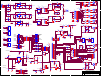
Theory of Operation – Automatic Switcher Circuit.
The AES-302 is designed to operate in automatic and manual switching modes. Upon application of power
the unit defaults to the manual mode. In this mode switching between channels can only be accomplished
by pressing the desired channel button or commanding the desired remote control pin. With power
application C37 pulls the clock pin 3 of U6A low thus placing the IC in the reset mode whereby pin 1 Q
output is pulled low. This in turn cuts off Q2 preventing automatic switching from occurring. Depressing
the “Auto” front panel button places the unit in automatic operation. The actuation of the “Auto ” button
places a high on pin 6 of U6A which in turn sets Q output high enabling Q2. When an error or silence
sense timeout occurs, a delay of approximately 3 seconds is provided via U16 LM741 which acts as a
comparator. Once the delay of U16 times out the comparator flips pulling the base of Q4 low which
saturates Q3 momentarily. Momentary operation of Q3 is due to C45 being in an initially discharged state.
When Q3 is turned on C45 begins to charge enabling Q3 to pass current. This same current passes through
Q2 whose collector is routed to the proper coil of K1, which is the signal routing relay. K1 fires and
switches to the alternate path. No further switching will occur because the error signal is still present on the
base of Q4. This error signal will remain until the error-reset button is pressed. Once the reset occurs, U16
changes output state back to a positive condition which causes Q4 to be saturated. Once Q4 saturates Q3 is
cutoff and C45 begins to discharge through R32. CR19 prevents unintentional operation of the automatic
switch circuit when errors are reset by momentarily cutting off Q2. C38 aids in preventing unintentional
operation by holding the base of Q2 low until the error has had sufficient time to clear.
The silence sensor accepts audio from the left/right output of the AES-300 module via jumpers J-1 and J-2.
To select both channels place both jumpers in the position closest to the front of the unit. For left channel
only place only J1 in the forward position. For right only place J2 in the forward position. The audio is
then amplified by U15A and is rectified by CR20. The D.C. output of CR20 is then fed to C56 which
stores the D.C. sample until a loss of audio occurs. Once loss of audio is encountered, C56 begins to
discharge through R56 and/or R59. After a time delay of 30 or 60 seconds U15B-7 goes negative and is
clamped by CR22 to 0 volts D.C. This 0 volt indication causes CR21 to conduct pulling the base of Q4 low
which initiates the switching action as described above. If silence sensing is not desired, place S6-6 in the
off position.
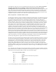
Any or all of the errors that appear on the front panel display can be made to actuate a switching operation.
Factory default is all error and silence sensing selected. To change this configuration, remove the top cover
and locate S6 on the motherboard. Refer to table 1 below for switch settings:
Error Switch Actuation Table 1
S6-1 Coding
S6-2 Unlock (must be selected for auto operation)
S6-3 Parity
S6-4 CRC
S6-5 Slipped Sample
S6-6 Silence Sensor
S6-7 30 seconds *
S6-8 60 seconds
* For 30 second delay place both S6-7 and S6-8 in the “On” Position