
Specifications


e-mail: support@broadcasttools.com voice: 360.854.9559 fax: 866.783.1742
4
2x10 DA Installation and Operation Manual
INSTALLATION
INSTALLATION
Please examine your 2x10 DA carefully for any damage that may have been sus-
tained during shipping. If any are noted, please notify the shipper immediately and
retain the packaging for inspection by the shipper. The package contains the 2x10
DA, 16vAC only @ 600ma wall power transformer, one daisy-chain power cable
and this manual.
Installation of the 2 x 10 DA in high RF environments should be performed with
care. Shielded cable is suggested for all audio connections. All shields should be
tied to the “GND” Ground terminals. The station ground should be connected to the
chassis ground screw located on the far right side of the 2 x 10 DA as viewed from
the rear. It is recommended that all cables connected to the 2 x 10 DA be looped
through ferrite cores to suppress RF.
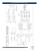
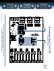
Note: Refer to the Appendix for component layout and fractional schematics.
Input Gain: The internal input gain jumpers JP4-5 set the left channel gain, while
JP6-7 set the right channel gain. Follow the silk-screened labels on the PCB for the
correct gain settings. The factory default setting is +4dBu.
LT/RT Act Led’s: The front panel led’s indicating left and right input audio activity.
Monaural setting: Each stereo output has a MONO jumper. Follow the silk-
screened labels on the PCB. If the jumper is installed, that output will be combined
to monaural. Placing a jumper over JP1 converts output one to mono, JP2 output
two, JP3 output three, JP8 output four and JP9 addresses output five. The factory
setting is Stereo. The five stereo outputs operate independently; setting one output
pair to MONO, does not degrade the integrity of the other stereo outputs. Each out-
put has a front panel gain adjustment for setting output levels.
Inputs: Connect your audio source to the 2 x 10 DA inputs. The left input is labeled:
“INL- INL+" and the right input is labeled: "INR- INR+". For unbalanced inputs,
install a jumper between the "-" input and GND. Single (mono) inputs may be fed
to all output channels by connecting the left and right inputs in parallel.
Outputs: Connect each left load to the 2 x 10 DA outputs; labeled: 1L-/1L+, 2L-
/2L+, 3L-/3L+, 4L-/4L+ and 5L-/5L+". Connect each right load to the 2 x 10 DA
outputs; labeled: 1R-/1R+, 2R-/2R+, 3R-/3R+, 4R-/4R+ and 5R-/5R+" For
unbalanced loads, use the "+" and GND terminals only.
Do not connect the "-" terminal to ground. Shields should be tied to the “GND”
terminals.
WEBSITE:
Visit our web site for
product updates and
additional information.