VEEMUX® Series SM-nXm-DVI(A)-LCD DVI Video Matrix Switch Installation and Operation Manual MAN124 Rev Date 10/8/2013
TRADEMARK VEEMUX is a registered trademark of Network Technologies Inc in the U.S. and other countries. COPYRIGHT Copyright © 2010, 2013 by Network Technologies Inc. All rights reserved. No part of this publication may be reproduced, stored in a retrieval system, or transmitted, in any form or by any means, electronic, mechanical, photocopying, recording, or otherwise, without the prior written consent of Network Technologies Inc, 1275 Danner Drive, Aurora, Ohio 44202.
TABLE OF CONTENTS Introduction.................................................................................................................................................................... 1 Supported Web Browsers............................................................................................................................................ 1 Materials ............................................................................................................................................
DDC Options........................................................................................................................................................ 41 Hot Plug Options ................................................................................................................................................. 42 DDC Mix ..............................................................................................................................................................
iv
NTI VEEMUX DVI VIDEO MATRIX SWITCH INTRODUCTION The VEEMUX DVI Video Matrix switch (VEEMUX) provides non-blocking access to 4, 8, 16, or 32 single link digital DVI video sources from 4, 8, 16, or 32 displays. Locate computers up to 19 feet away from displays, enabling easy access to multiple servers in various locations. The “n” in the part number SM-nXm-DVI-LCD represents the number of displays. The “m” in the part number represents the number of video sources.
NTI VEEMUX DVI VIDEO MATRIX SWITCH MATERIALS Materials supplied with this kit: • • • • • • • • • • NTI SM-nXm-DVI-LCD DVI Video Matrix Switch Power Cord- country specific IRT-UNV Remote Control CT6182 DB9 Female-to-RJ45 Female adapter CB4352- 5 foot CAT5 patch cable Rack mount kit (2 Mounting ears (MP3180-4X4; MP4041-8X8), 6 screws-HW6137) (4X4 and 8X8 only) 4pcs #10-32 x 3/4" pan head screws and #10-32 cage nuts (server cabinet mounting hardware) CD containing pdf of this manual and control software zip
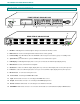
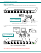
NTI VEEMUX DVI VIDEO MATRIX SWITCH FEATURES AND FUNCTIONS FRONT VIEW OF SM-8X8-DVI-LCD System Reset IR OUT: 1 2 3 4 IN: 1 2 3 4 1 5 3 4 1 2 3 NTI 4 R Network Technologies Inc 5 Menu 1 2 3 4 2 6 6 Out 7 8 5 6 7 VEEMUX R 8 In 7 8 12 REAR VIEW OF SM-8X8-DVI-LCD OUTPUT 8 OUTPUT 7 OUTPUT 6 OUTPUT 5 OUTPUT 4 OUTPUT 3 OUTPUT 2 OUTPUT 1 INPUT 8 INPUT 7 INPUT 6 INPUT 5 INPUT 4 INPUT 3 INPUT 2 INPUT 1 RS232 (DCE) ETHERNET R J45 "< US B > " R J45 "< US B > "
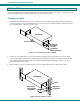
NTI VEEMUX DVI VIDEO MATRIX SWITCH INSTALLATION This NTI switch was designed to be mounted to a rack or to set on a desktop. It includes rack mount ears to make attachment to a rack easy, and rubber feet to be applied to the bottom of the case if it will instead sit on a flat surface. If this will sit on a flat surface, simply apply the rubber feet to the bottom of the case in each of the 4 corners. To Mount to a Rack 1.
NTI VEEMUX DVI VIDEO MATRIX SWITCH Make All Connections 1. Connect a DVI male cable (15 feet maximum) between each video source and an “Input” connector on the rear of the VEEMUX.
NTI VEEMUX DVI VIDEO MATRIX SWITCH 3.If the VEEMUX will be controlled using RS232, then make a connection between the “RS232” port on the VEEMUX and a serial port on a PC. A DB9M-to-RJ45F adapter and 5 foot CAT5 patch cable have been provided to help with this connection if needed.
NTI VEEMUX DVI VIDEO MATRIX SWITCH 4. To make a remote connection, over the Ethernet, from anywhere on the local area network, connect a CAT5/5e/6 Ethernet cable with RJ45 male connectors on the ends, wired straight through (pin 1 to pin 1, pin 2 to pin 2, etc.).
NTI VEEMUX DVI VIDEO MATRIX SWITCH Audio Connections If this VEEMUX model has audio support, then connect 3.5mm cables from each audio source to the “AUDIO IN” ports and 3.5mm cables from self-powered stereo speakers to the “AUDIO OUT” ports.
NTI VEEMUX DVI VIDEO MATRIX SWITCH OPERATING THE VEEMUX The VEEMUX video matrix switch has four methods of control: • Front Panel LCD with Keypad • Directly via an RS232 Interface • Remotely via Ethernet • Infrared Remote (optional). Every unit comes standard with all control methods built-in. An IRT-UNV-IR Remote Control is required (purchased separately) to use the Infrared option. No software is involved (see Infrared Control on page 49).
NTI VEEMUX DVI VIDEO MATRIX SWITCH To quickly change a connection, simply press an Out number followed by an In number corresponding to the display device you want to connect to the video source. Whether the Out-x button or the In-x button is pressed first doesn’t make a difference. To configure the VEEMUX, use the Menu keys.
NTI VEEMUX DVI VIDEO MATRIX SWITCH DDC Menu DDC enables the video source to get EDID information from the display device. This enables the video source to automatically select the optimal resolution for the display by receiving, at power up, information from the display device concerning its resolution specifications.
NTI VEEMUX DVI VIDEO MATRIX SWITCH Models SM-16X16-DVI-LCD and SM-32X32-DVI-LCD The keypad control for the 16X16 and 32X32 models is very similar to that of the 8X8, with these differences: • • • The “In” and “Out” ports are selected by pressing the associated port number and then the “In” or “Out” button to designate the video source or the display (respectively). Alternatively, the “In” or “Out” button can be pressed, then the port number, followed by the “Enter” button.
NTI VEEMUX DVI VIDEO MATRIX SWITCH USB Console Port If your VEEMUX is model SM-4X4-DVI(A)-LCD and you have connected a USB cable between the VEEMUX and your PC (page 6), you will be able to control your VEEMUX serially from a terminal console using this connection. Installing Drivers You will only need to install drivers the first time the VEEMUX is connected to your PC. After the first time, when the VEEMUX is connected your PC should recognize the VEEMUX and re-assign the COM port.
NTI VEEMUX DVI VIDEO MATRIX SWITCH C. Let the New Hardware Wizard search for the driver, but direct it to the drive the Product Manual CD is in and the directory of either the 32 bit driver or the 64 bit driver. D. Once the driver is installed, you will get this screen and the VEEMUX USB Console Port will be ready to use. .
NTI VEEMUX DVI VIDEO MATRIX SWITCH Windows 7-64 bit Installation A Windows 7 64 bit installation has a few extra steps. The images below are from a Windows 7, 64-bit installation. A. Upon VEEMUX power ON, the driver cannot be found. Press “Close”. B. Open the Device Manger and select the VEEMUX in the device list. Right-click and open “Properties”. Select “Update Driver Software”. C. From the next window, select “Browse my computer for driver software” .
NTI VEEMUX DVI VIDEO MATRIX SWITCH E. You will probably get this warning that Windows can’t verify the publisher of the driver software. Select “Install this driver software anyway. “ F. The driver will load. This might take a minute while it searches your computer for the usbser.sys file it needs. Once it does, you will get a window telling you Windows is finished. Take note of the COM port number it assigned. (This one assigned COM3.
NTI VEEMUX DVI VIDEO MATRIX SWITCH 4. During the installation, your PC will assign a COM port number to the USB port attached to the VEEMUX. You will need to identify the COM port number assigned. This information can be viewed in your Device Manager list (below) if you didn’t take note of it during installation. COM Port Assignment Figure 10- COM port assigned to VEEMUX Using the USB Console Port The virtual COM port will be used to enable serial control over the VEEMUX (see RS232 control on page 18).
NTI VEEMUX DVI VIDEO MATRIX SWITCH RS232 CONTROL RS232 enables the VEEMUX to be remotely controlled via RS232.
NTI VEEMUX DVI VIDEO MATRIX SWITCH CPU RS232 Serial Port Matrix-Y-1 Matrix-Y-1 Matrix-Y-1 RJ45 TO DB9 SERIAL ADAPTER RJ45 TO DB9 SERIAL ADAPTER CAT5 CABLE Note: The maximum combined RS232 cable length between the CPU and any NTI switch cannot exceed 15 feet.
NTI VEEMUX DVI VIDEO MATRIX SWITCH Command Protocol CPU controller commands supported by the unit are defined below. All commands must be terminated with a (carriage return). When a command is sent, the entire string is echoed back along with a response from the addressed unit as shown in the Command Definitions table (below). All characters in the command string are case sensitive (see Command Definitions table), and all numbers below 10 must have a leading 0 (ex: 1 = 01).
NTI VEEMUX DVI VIDEO MATRIX SWITCH Additional Command Definitions for Audio Option Command String Good Response Description AS SW,IP,OP * AUDIO Connect One Output/User Port To Input/CPU Port AA SW,IP * AUDIO Connect All Output/User Ports To Input/CPU Port AO SW,OP *IP AUDIO Read Connection For Output/User Port AM SW,OP,MU * Set Mute State For Output/User Port AV SW,OP,VV * Set Volume Level For Output/User Port See chart on page 21 for values AR SW,OP *MU,VV Read Mute, Volume
NTI VEEMUX DVI VIDEO MATRIX SWITCH SerTest- RS232 Interface Test Program This software allows a user to test the functions of an NTI server switch, matrix switch or Multi-user/Multi-platform switch RS232 interface. The SerTest program is automatically loaded when installing the Matrix Switcher’s Control Program as described above.
NTI VEEMUX DVI VIDEO MATRIX SWITCH Setup Options Key 1) 2) 3) 4) Selection select Com port current: (COM1:) select Baud rate current: (9600) set unit Address current: (1) set read timeout (5) Description - select PC serial port - the current PC serial port is displayed in parentheses - select PC serial port baud rate - the current baud rate is displayed in parentheses - select the unit address - the current address is displayed in parentheses - select the time period (in seconds) the SerTest will wait fo
NTI VEEMUX DVI VIDEO MATRIX SWITCH ETHERNET CONTROL Telnet Interface-Port 2000 The Telnet Interface enables the user to control the switch using telnet client through an Ethernet connection. The telnet server listens on ports 2000 and 2005. Port 2000 is for an operator telnet session while port 2005 (must be enabled) is intended for a software control type session (see page 26).
NTI VEEMUX DVI VIDEO MATRIX SWITCH Command Reply Description Gs nn * dwt Read set Scanning Sequence dwell time value (dwt) for specific Output (nn) in seconds (see also "Scanning Sequences" on page 38) Sa nn,mm * Set scan list of individual output nn to all inputs mm Sc nn * Clear scan list of individual output nn S+ nn,mm * Add input mm to Scan List of output nn S- nn,mm * Remove input mm from Scan List of output nn Sx nn *oooxoxxxooooxxx Display the Sca
NTI VEEMUX DVI VIDEO MATRIX SWITCH Telnet Interface-Port 2005 For a software control type of telnet interface session (versus operator telnet control through port 2000 as described on page 24), connect to the VEEMUX through the current IP address at port 2005. Use the command set below to control and acquire information from the VEEMUX. Note: After establishing the connection, the unit will answer with a blinking prompt on the next line.
NTI VEEMUX DVI VIDEO MATRIX SWITCH Command Detail RU-Read Unit Size Command: Byte 1 Byte2 Byte3 ‘R’ (0x52) ‘U’ (0x55) (0x0D) Response: Byte 1 Byte 2 Byte 3 Byte 4 Byte 5 Byte 6 ‘r’ (0x72) Space (0x20) Input – 1st digit (0x30…0x32) Input – 2nd digit (0x30…0x39) ‘,’ (0x2C) ‘u’ (0x75) Byte 7 Byte 8 Output – 1st digit Output-2nd digit (0x30…0x32) (0x30…0x39) Byte 9 (0x0D) This command will read the size of the unit.
NTI VEEMUX DVI VIDEO MATRIX SWITCH SS_01- Enable Auto Status Mode Command: Byte 1 Byte 2 Byte 3 Byte 4 Byte 5 Byte 6 ‘S’ (0x53) ‘S’ (0x53) Space (0x20) ‘0’ (0x30) ‘1’ (0x31) (0x0D) Response: Byte 1 Byte 2 ‘∗’ (0x2A) (0x0D) Auto status mode is disabled by default whenever the connection is established, and this command must be entered to enable it. When auto status mode is enabled, a message will be sent whenever an input/output connection changes from any source.
NTI VEEMUX DVI VIDEO MATRIX SWITCH AO-Read Audio Connection for Output Port Command: Byte 1 Byte 2 Byte 3 Byte 4 Byte 5 Byte 6 ‘A’ (0x41) ‘O’ (0x4F) Space (0x20) Output – first digit (0x30…0x32) Output – second digit (0x30…0x39) (0x0D) Byte 1 Byte 2 Byte 3 Byte 4 Byte 5 Byte 6 Byte 7 Byte 8 Byte 9 ‘a’ (0x41) ‘c’ (0x63) Space (0x20) Output – 1st digit Output – 2nd digit Input – 2nd digit (0x30…0x39) ‘,’ (0x2C) Input – 1st digit (0x30…0x32) (0x30…0x32) (0x30…0x39)
NTI VEEMUX DVI VIDEO MATRIX SWITCH AV- Set Audio Volume for Output Port Command: Byte 1 Byte 2 Byte 3 Byte 4 Byte 5 Byte 6 Byte 7 Byte 8 Byte 9 ‘A’ (0x41) ‘V’ (0x65) Space (0x20) Output – 1st digit Output – 2nd digit (0x30…0x32) (0x30…0x39) ‘,’ (0x2C) Volume – 1st digit (0x30…0x32) Volume – 2nd digit (0x30…0x39) (0x0D) Response: Byte 1 Byte 2 ‘∗’ (0x2A) (0x0D) This command sets the volume specified audio output port to the specified level (00 – 99).
NTI VEEMUX DVI VIDEO MATRIX SWITCH Web Interface A user may control the connections of the VEEMUX using a Web Interface via any web browser (see page 1 for supported web browsers). With the VEEMUX connected to a LAN through an Ethernet cable, a user can access the web interface controls inside the VEEMUX. FYI: To quickly locate a VEEMUX on the LAN and edit the IP address settings, use the Device Discovery Tool (page 48).
NTI VEEMUX DVI VIDEO MATRIX SWITCH With a successful login, the main menu and Video Switch page will appear. Main Menu The VEEMUX main menu provides control over all functions of the switch. The administrative menu includes options not available to other users with limited privileges. When logged in a user without administrative privileges, only the SWITCH, LOGOUT, and SUPPORT menu options will be available. For more on user management, see page 40.
NTI VEEMUX DVI VIDEO MATRIX SWITCH Video Switch Page The Video Switch page (Figure 16) displays the active connections (shown in orange) and enables the user to control the video connections of the VEEMUX. Up to 100 different connection configurations can be saved and later recalled by any connection method. Scanning Sequences (page 38) for each output can also be enabled.
NTI VEEMUX DVI VIDEO MATRIX SWITCH Administration The Administration section provides links to pages for all configuration options in the VEEMUX switch. Only the user ROOT and users with administrative privileges have access to this section.
NTI VEEMUX DVI VIDEO MATRIX SWITCH Network Configuration ON the Network Configuration page, under Administration, the administrative user can configure the VEEMUX web interface connection. This will provide access to control of the VEEMUX from any web-accessible computer. Figure 18- Network Configuration page Mode – Choose between Static IP assignment, DHCP (dynamic IP assignment) or Disable the Ethernet port entirely.
NTI VEEMUX DVI VIDEO MATRIX SWITCH If telnet is going to be used to control the VEEMUX, place a checkmark in the “Enable Telnet” block. If you wish to disable non-secure web access to the VEEMUX, remove the checkmark from “Allow HTTP Access”. this box empty, only secure shell web access will be allowed. With A standard port number can be assigned for the HTTP (non-secure) and HTTPS (secure) ports, numbers ranging from 065535. Default HTTP port is 80, and default HTTPS port is 443.
NTI VEEMUX DVI VIDEO MATRIX SWITCH Video Output Names From the Administration menu, the Output Names page can be displayed. This page enables the Administrator to change the names of the output ports displayed on the Switch page. Figure 20- Video Output Names page To change an Output Name, enter the name of the port for the desired output port number, and press "Save". If you make changes and change your mind and want to return the names back to what they were before changing them, press “Reset”.
NTI VEEMUX DVI VIDEO MATRIX SWITCH Scanning Sequences From the Administration menu, the Scanning Sequence page can be displayed. The Scanning Sequence page displays the configuration of an automatic switching sequence from input (video source) to input for each output (monitor).
NTI VEEMUX DVI VIDEO MATRIX SWITCH Example of using Outputs Scanning Sequences Problem: A synchronous scan is desired for all outputs with a dwell time of 3 minutes per input, and no two outputs should be looking at the same input at any given time. Solution: 1. Set the dwell time for all inputs listed in each output at 180 seconds (3 minutes). Press “Save” each time changes are made to the selected output. . 2.
NTI VEEMUX DVI VIDEO MATRIX SWITCH User Config From the Administration menu, select the User Config to display a list of the users that have been configured on the VEEMUX. - To add a user, select “Add New User”. To change the configuration of a user, select the Username, or “Edit”. To delete a user, select “Delete” for that user. Figure 22- Users page Whether you add a user, or edit a user, the “Configure User” page will open.
NTI VEEMUX DVI VIDEO MATRIX SWITCH DDC Options From the Administration menu, the DDC Options page can be displayed. DDC enables the video source to get EDID information from the display device. This enables the video source to automatically select the optimal resolution for the display by receiving, at power up, information from the display device concerning its resolution specifications.
NTI VEEMUX DVI VIDEO MATRIX SWITCH Notes: 1. A Blu-Ray player, and any other video source with protected content, must use "Direct" DDC option and can be connected to only one output port at a time. 2. In order for the video sources to correctly receive the EDID information from the switch at boot-up, the switch must be powered-up before all attached video sources. 3. If “Disable Toggle HP” is checked for any Input port, the changes made for that port will not take immediate effect when “Save” is pressed.
NTI VEEMUX DVI VIDEO MATRIX SWITCH Video Optimization (Applicable to models 4x4, 16x16, and 32x32 only) From the Administration menu, the Video Optimization page can be displayed. This page enables the administrator to improve the video quality of a PC (input) as viewed on a monitor (output). Note: It is not recommended that the user change the video quality of a connection while in the web interface on that connection.
NTI VEEMUX DVI VIDEO MATRIX SWITCH Update Firmware From the Administration menu, the Update Firmware page can be displayed. The Update Firmware page shows the current version of the firmware and enables the Administrator to update the firmware to the latest version available. Note Version Number Here Figure 27- Update Firmware page WARNING: Failure to carefully follow these directions can permanently damage the VEEMUX. Please read these directions in full before continuing.
NTI VEEMUX DVI VIDEO MATRIX SWITCH Standby Mode From the menu, the user can quickly place the VEEMUX in Standby Mode. When in Standby, the VEEMUX will still be poweredON but all functions will stop. The VEEMUX will be in a power-saving ready-to-use state. Figure 28- VEEMUX in Standby Mode By simply selecting “Standby” from the side menu, the VEEMUX is placed in Standby Mode.
NTI VEEMUX DVI VIDEO MATRIX SWITCH Support The Support link on the menu drops down to two choices, Manual and Downloads. The Manual link will open the pdf manual for the VEEMUX. The Downloads link will open the firmware downloads page for the SM-8X8-DVI Video Matrix Switch at NTI. From there you can see what versions of firmware are available and determine if the version in your VEEMUX is current or in need of an upgrade (page 44).
NTI VEEMUX DVI VIDEO MATRIX SWITCH Web Interface With Audio Support Models with audio support have additional control built in. An additional web page is provided to separately control audio connections if so desired. Control connections together or separately Volume Control Figure 32- Audio Switch page There is a checkbox provided that allows the user to choose between controlling audio along with video connections, or controlling them separately.
NTI VEEMUX DVI VIDEO MATRIX SWITCH DEVICE DISCOVERY TOOL In order to easily locate the VEEMUX on a network, or to change network settings, the NTI Device Discovery Tool may be used. A link to the Discovery Tool is provided on the web page that appears when you insert the instruction manual CD provided into your CD ROM drive. Click on the link or browse the CD and click on the file discover.html . This will open your browser and display the Device Discovery Tool page.
NTI VEEMUX DVI VIDEO MATRIX SWITCH INFRARED REMOTE CONTROL The IRT-UNV Infrared Remote Control allows the user to remotely and intuitively control up to 15 NTI SM-nXm-DVI(A)-LCD DVI video matrix switches, providing the ability to route connections, save and recall switch configurations, and put the switch into Standby.
NTI VEEMUX DVI VIDEO MATRIX SWITCH Buttons The IRT-UNV Infrared Remote Control user interface consists of a keypad with 29 buttons.
NTI VEEMUX DVI VIDEO MATRIX SWITCH • AUDIO (Applies to models with audio support only) Pressed prior to entering a port switch command Applies the command to the audio signals only (by default, port switch commands are applied to both Audio and Video) • VOL + / (Applies to models with audio support only) Increases / Decreases the volume for the selected output Can be used with * (All) to adjust the volume for all outputs “Volume +” and ”Volume -“ will operate as multi-press buttons – if contin
NTI VEEMUX DVI VIDEO MATRIX SWITCH Examples: Change connection of Output 1 from Input 1 to Input 3: + <1> + wait 2 seconds + + + <1> + + + (must press within 5 seconds of pressing ) <1> + + + (must press within 5 seconds of pressing ) Jump To Input With the output port selected, a user knowing the desired input port number can enter it using the Numeric keys (0-9).
NTI VEEMUX DVI VIDEO MATRIX SWITCH Save and Recall The SM-8X8-DVI-LCD video matrix switches provide the ability to save and recall up to 10 switch configurations (up to 100 in the 16X16 and 32X32 models). The switch configurations define the current port connections, volume control settings, and video blank status. The IRT-UNV IR Remote can be used to access these configurations by using the “SAVE” and “RECALL” buttons.
NTI VEEMUX DVI VIDEO MATRIX SWITCH Technical Specifications For IRT-UNV Number of Controllable Systems Pushbutton Control Power supply Chassis material Approvals Max: 15 29 keys 2x AAA Battery Plastic RoHS Troubleshooting the IRT-UNV PROBLEM IRT-UNV is not selecting outputs or inputs • • SOLUTION Check battery The IRT-UNV may be configured to control the wrong switch- see “Multiple Switch Control” above. Troubleshooting the VEEMUX PROBLEM VEEMUX will not boot up SOLUTION 1.
NTI VEEMUX DVI VIDEO MATRIX SWITCH GENERAL TECHNICAL SPECIFICATIONS Video Video Amplifier Bandwidth 165MHz Input Video Signal 1.2 volts p-p Input DDC Signal 5 volts p-p (TTL) Single Link Range 1080p/1920 x 1200 DVI Connector DVI-I 29 pin female Audio (Audio Switches Only) Audio Connector 3.5mm jack Audio Signal Type Stereo unbalanced Audio: Frequency response 20Hz to 20kHz, +/- 0.5dB THD + N 0.
NTI VEEMUX DVI VIDEO MATRIX SWITCH INDEX optimize video.................................................................... 42 password ........................................................................... 31 rack mounting ...................................................................... 4 reboot................................................................................. 45 Restore .............................................................................. 34 RS232 pinout ...............