INC ® Installation and Operation Manual SS 4x4 Stereo Audio Matrix Switcher Firmware Version 1.07 Manual Update: 04/15/2009 Due to the dynamic nature of product design, the information contained in this document is subject to change without notice. Broadcast Tools, Inc., assumes no responsibility for errors and/or omissions contained in this document. Revisions of this information or new editions may be issued to incorporate such changes.
SS 4x4 Installation and Operation Manual Table of Contents Section Title Page # Introduction. . . . . . . . . . . . . . . . . . . . . . . . . . . . . . . . . . . . . . . . . . . . . . . . . . . . . . . 3 Safety Information . . . . . . . . . . . . . . . . . . . . . . . . . . . . . . . . . . . . . . . . . . . . . . . . . 3 Who to Contact for Help . . . . . . . . . . . . . . . . . . . . . . . . . . . . . . . . . . . . . . . . . . . . 3 Product Description . . . . . . . . . . . . . . . . . . . . . . . . . .
SS 4x4 Installation and Operation Manual INTRODUCTION Thank you for your purchase of a Broadcast Tools® SS 4.4 Four Input, Four Output Stereo Audio Matrix Switcher (referred to as the SS 4.4 throughout this manual). We’re confident that this product will give you many years of dependable service. This manual is intended to give you all the information needed to install and operate the Broadcast Tools® SS 4.4.
SS 4x4 Installation and Operation Manual Product Description The Broadcast Tools® SS 4.4 provides matrix audio switching of 4 stereo inputs to 4 stereo outputs. Matrix switching allows any/or all inputs to be assigned to any/or all outputs. The SS 4.4 may be controlled via front panel switches, contact closures, open collectors, logic and/or the multi-drop RS-232 serial port (USB or Ethernet optional). Installation is simplified with plug-in euroblock screw terminals.
SS 4x4 Installation and Operation Manual Function Description Front Panel The SS 4.4 is a 1-rack unit device (19”w x 1.75”h x 6.0”d). The front panel supports 19 selection switches, 24 LED indicators, headphone, powered monitor and LED VU meter selection switch, ¼” T/R/S jack and level controls. Rear Panel Installation is simplified with plug-in euroblock screw terminals.
SS 4x4 Installation and Operation Manual Controls Front panel powered monitor level control. Front panel headphone level control. Audio Inputs Each of the four stereo inputs are balanced bridging (20KΩ) at a nominal line level of +4dBu. Ample system gain is provided to accommodate most unbalanced consumer level products. Multi-turn level trimmers are provided for each channel. Audio Outputs The SS 4.4 provides four balanced low impedance stereo outputs.
SS 4x4 Installation and Operation Manual Serial Communication The SS 4.4’s serial communication is supplied with a multi-drop RS-232 port, allowing up to four SS 4.4’s on the same computers serial port. Commands may be entered either via a menu (menu mode) or a short form code (ASCII serial stringburst mode). All commands and responses use normal ASCII characters, facilitating scripting.
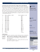
SS 4x4 Installation and Operation Manual Address (Unit ID) DIP Switches Switch-1 Switch-2 Mode OFF OFF ID = 0 ON OFF ID = 1 OFF ON ID = 2 ON ON ID = 3 Baud Rate DIP Switch Switch 3 Mode OFF 9600 ON 38400 Audio Switch Mode DIP Switch 4 Switch 5 OFF OFF ON OFF OFF ON ON ON Switches Mode Overlap Interlock Interlock MIX Open Collector/Relay Mode DIP Switch Switch 6 Function OFF Burst mode control. ON Follow / MUX mode.
SS 4x4 Installation and Operation Manual Mounting The SS 4.4 is designed to be rack mounted in a standard 19” rack. It should be mounted in an area that is accessible from the rear and preferably away from sources of heat. We recommend before permanently installing the SS 4.4, you bench test and become familiar with the operation of the unit.
SS 4x4 Installation and Operation Manual Connecting the remote control, PIP / Trigger Inputs and OC/Relays Most front panel functions of the SS 4.4 may be remote controlled via the pluggable euroblock screw terminals located on the rear panel. The SS 4.4 accepts momentary contact closures; open collector or TTL/CMOS input logic levels. Open collectors and relay connections are provided on the lower rear panel 18 position connector TB-6. Each relay and/or open collector and mute input is labeled.
SS 4x4 Installation and Operation Manual Adjusting Input and Output Levels Once the input and output connections have been made, the input levels can be set. The switcher is factory set for unity, but has about 10 dB of system gain. Recommended input levels would be in the range of -6 dBu to +10 dBu. Should input levels need to be changed, they are accessible from the rear panel. Each stereo input and output is labeled and have two trimmers per stereo channel.
SS 4x4 Installation and Operation Manual Connecting Two SS 4.4’s To A Single Computers Serial Port Multiple SS 4.4’s may be cascaded serially to operate from the same serial port. The first step is to assign unit ID’s to each SS 4.4. One suggestion is to assign unit ID 1 to the first SS 4.4 and unit ID 2 to the second switcher. The second step is to parallel the serial ports of the SS 4.4’s.
SS 4x4 Installation and Operation Manual Operation Guidelines Front Panel LED’s Number Front Panel LED’s Of LED’s Activation Event/Mode Input connected to “OP 1” 4Green State of connection ON if connected Input connected to “OP 2” 4 Green State of connection ON if connected Input connected to “OP 3” 4 Green State of connection ON if connected Input connected to “OP 4” 4 Green State of connection ON if connected “MUTE” 1 Green ALL inputs are OFF ON “MACRO” 1 Green Flickers when active “A
SS 4x4 Installation and Operation Manual SS 4.4 Front Panel switch operation Action Push the desired Input switch in the “OP-1” area. Push the desired Input switch in the “OP-2” area. Push the desired Input switch in the “OP-3” area. Push the desired Input switch in the “OP-4” area. Switches Input channels 1 through 4 for each four-outputs. “MUTE” “MACRO” “MON” Result The selected input is connected to output 1.
SS 4x4 Installation and Operation Manual The command to enter menu mode is: *0MM. The menu mode displays certain parameters, and allows for the control and/or configuration of most switcher functions. Serial Burst Mode Commands Burst mode allows a computer or ASCII terminal to control and interrogate the unit. This section defines all burst mode commands. Each burst mode commands starts with an asterisk (*). Next is a single decimal digit that corresponds to the unit (ID) address 0-3.
SS 4x4 Installation and Operation Manual Glossary Of Command Notation Character String Meaning u Unit ID ii Input Number o Output Number r Output Relay o Open Collector Allowable Values 0-3 01-04 1-4 1-4 1-4 Set-up Commands *uMM - Open up Menu *uCEx - Enable Error and Good Responses - Where x = Y to enable and N = disable. In this mode, when a command is sent that is in error, the unit will reply (possibly before receiving the entire command) with “EEE.
SS 4x4 Installation and Operation Manual Relay and Open Collector Commands *uOOoF - Unlatch open collector “o” (Only works in NON-Remote mode *uOOoL - Latch open collector “o” (Only works in NON-Remote mode *uOOoP - Pulse open collector “o” (Only works in NON-Remote mode Audio Switch Control Commands *uiio - Apply input “ii” to output “o” *uiiA - Apply input “ii” to ALL outputs *uiiEott - Start overlap - Apply input ii to output o. After tt tenths of a second, remove all other inputs from output o.
SS 4x4 Installation and Operation Manual Special MIX mode commands (the switcher doesn’t need to be in MIX mode).
SS 4x4 Installation and Operation Manual Specifications Input Levels: Output Levels: System Gain: Frequency Response: * Signal/Noise Ratio: * Distortion: * IMD (250/7kHz): * Crosstalk: * Input expansion port: Switching Method: Logic: Operation Control: Status/Control: Interfacing: Power: Mechanical: Weight: * Audio Precision Test Equipment Max + 27 dBu, balanced, bridging. 20k Ω. Four stereo balanced outputs, +24 dBm. @ 600 Ω. / +27dbu @ 10KΩ. Powered monitor unbalanced output, 0 dBm. @ 600 Ω.
SS 4x4 Installation and Operation Manual LIMITED WARRANTY The term “Buyer” as used in this document refers to and includes both (but only) (a) any person or entity who acquires such an item for the purpose of resale to others (i.e., a dealer or distributor of an item), and (b) the first person or entity who acquires such an item for such person’s or entity’s own use.