INC ® Installation and Operation Manual WVRC-4 Four Channel Web Voice Dial-up Remote Control System Network Agent Version 3.68 Manual Update: 07/13/2011 PIC Firmware Version 1.12 or above CAUTION! The following information pertains to the above version(s) of firmware. If your unit is not loaded with this version of firmware, please contact Broadcast Tools for an upgrade. Due to the dynamic nature of product design, the information contained in this document is subject to change without notice.
WVRC-4 Installation and Operation Manual Table of Contents Section Title Page # Introduction .........................................................................................................................3 Safety Information...............................................................................................................3 Who to Contact for Help .....................................................................................................4 Product Overview...................
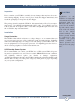
WVRC-4 Installation and Operation Manual INTRODUCTION Thank you for your purchase of a Broadcast Tools® WVRC-4, Four Channel WEB and Voice Dial-up Remote Control System (referred to as the WVRC-4 throughout this manual). We’re confident that this product should give you many years of dependable service. This manual is intended to give you all the information needed to install and operate the Broadcast Tools® WVRC-4. SAFETY INFORMATION Only qualified technical personnel should install the WVRC-4.
WVRC-4 Installation and Operation Manual Product Overview The WVRC-4 provides a cost-effective, half-rack solution for web based and/or recordable voice response dial-up transmitter site control. The WVRC-4 was designed from a users point of view, so all of the basic functionality you need is included to control your site equipment, while including the accessories other manufacturers consider optional.
WVRC-4 Installation and Operation Manual Inspection Please examine your WVRC-4 carefully for any damage that may have been sustained during shipping. If any is noted, please notify the shipper immediately and retain the packaging for inspection by the shipper.
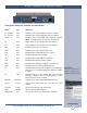
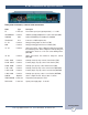
WVRC-4 Installation and Operation Manual Front panel indicators, controls and connectors Name Type Description K1 - K4 Raise LED Illuminates when corresponding raise relays are activated. K1 - K4 Lower LED Illuminates when corresponding lower relays are activated. Status 1 - 4 LED Illuminates when corresponding status inputs are activated. NOTE: Counting from the top (1) down to the bottom (4). TX LED Flashes during server/control processor data exchange.
WVRC-4 Installation and Operation Manual Rear panel indicators, controls and connectors Name Type PF 2.1mm Jack SSL/GND/SSR Connector Description Power Failure power jack (optically-isolated). 6 - 12 VDC.
WVRC-4 Installation and Operation Manual Connecting your WVRC-4 to other equipment Analog (metering) inputs CAUTION! Analog input (metering) samples may be elevated several hundred volts above ground on some external equipment. Permanent damage may occur to the WVRC-4 and/or external equipment if a high voltage metering source is connected to the WVRC-4! Failure to observe this warning may also cause injury to the installer or other personnel.
WVRC-4 Installation and Operation Manual Status Inputs Each of the four optically isolated status inputs can be configured to accept either a contact closure (dry = default) or a (floating, wet). Attach your dry contacts to the desired status channels StxA and STxB (where x is the status input) terminals. Each input is equipped with a four-position header. Each input is labeled IN-x (where x is the status input) and the header pins are labeled 1,2,3,4.
WVRC-4 Installation and Operation Manual TEMP Sensor Probe Input Insert the temperature probes (25 foot cable) mini (3.5mm) plug in to the rear panel jack labeled “TEMP” (-40°F to +190°F (-40°C to +85°C). NOTE: Please limit the total length of cable to 50 feet. Please contact the factory for the proper extension cable. The temperature probe should only be installed or removed with the power supply disconnected from the WVRC-4.
WVRC-4 Installation and Operation Manual Dial-Up Programming Connect the supplied 12VAC power supply cord in to the WVRC-4’s power jack labeled “12VAC 1 AMP”, then plug the transformer in to a source of 120 vac 60Hz. Verify that the green “PWR” led is illuminated. Follow the steps below to configure the WVRC-4 for dial-up operation: Installing factory (Dial-up only) defaults. Remove power from the unit. Hold down the “PGM” button down while reinstalling the power plug.
WVRC-4 Installation and Operation Manual 3 - Press the front panel “PGM” button. The front panel “PGM” LED will illuminate, while the program menu on the next page will be displayed: Program Menu: Menu navigation: Press escape (ESC) to jump back to the previous menu selection, and if pressed from the PGM Menu, program mode will be exited. Dial Out Numbers These are the numbers that will be dialed when alarms are generated.
WVRC-4 Installation and Operation Manual Dial-Out List When (2) is selected from the PGM Menu, the Dial-Out List is displayed. This is where you determine what number is dialed for a selected input alarm. 1 - 4 is used for status inputs, A-D are used for Analog (metering) inputs, S for Silence Sensor, P for Power Fail and T for Temperature. The numbers after the Analog letter selection show which analog channel is being selected.
WVRC-4 Installation and Operation Manual When item (3) is selected from the PGM Menu, the Access Code, Lap, Ring Count, Repeat Count, Silence Sensor Delay Time, Power Fail Time, Hang up time, Monitor access code and Analog Debounce Time can be programmed. The “Access Code” may be changed from the default code of 123, allowing a user all control functions.
WVRC-4 Installation and Operation Manual Pager Numbers and Data Strings When item 4 is selected from the PGM Menu, the pager number and pager data can be entered. To force the WVRC-4 to dial a pager number, enter a “9” in the dial-list.
WVRC-4 Installation and Operation Manual NOTE: The decimal point may be added and is not considered part of the four digits Example: To calibrate analog (metering) channel 1, enter 1, then the desired fourdigit reading. Example: 75.00 would be seventy-five; 750.0, seven hundred and fifty while 7500 would be seventy five hundred. NOTE: The correct value on the analog (metering) input MUST be present for several seconds prior to entering OP/PGM mode.
WVRC-4 Installation and Operation Manual Temperature alarm set points are set up in the analog (metering) “Alarms” menu section. Item “9” sets the low and high set points. The entry is a four-digit number with the first digit being the F or C designator. If the first digit is a “0” then the number is assumed to be Fahrenheit. If the first digit is a “1” then Celsius is assumed. Example: To enter low and high alarm set points of 30F and 95F, enter 0030/0095.
WVRC-4 Installation and Operation Manual When “2” is selected from the menu, the following is displayed: Make changes or press ESC to accept current values. If changes are made, all four values must be entered. Valid settings are 0 through 9. A “0” will turn off the status input so that it will not generate an alarm. A 1-9 will set the “DEBounce” period from 10 to 90 seconds. That means that the input must be in the alarm state continuously for that amount of time for an alarm to be generated.
WVRC-4 Installation and Operation Manual Here is a list of the voice messages that are included with the WVRC-4.
WVRC-4 Installation and Operation Manual Message Relay 1 Relay 2 Relay 3 Relay 4 Relay 5 Relay 6 Relay 7 Relay 8 Temperature Degrees Celsius Degrees Fahrenheit Minus Enabled Disabled Point Temperature Alarm Address 51 52 53 54 55 56 57 58 60 61 62 63 64 65 66 67 Length (Sec) 5 5 5 5 5 5 5 5 2.6 2.6 2.6 2.6 2.6 2.6 2.6 2.6 “CONFIGURE” DIP Switch settings: NOTE: The “UP” position is OFF DIP 1 - Feature creep DIP 2 - OFF = Voice Temperature in Fahrenheit, ON = Celsius.
WVRC-4 Installation and Operation Manual When the WVRC-4 is called, it will answer on the number of rings programmed. When it answers, enter the default security code 123 for this example. The access LED will illuminate once a valid security code is entered, and the “Access Accepted” Message will play. After a valid access code is received, the addressed unit will generate a DTMF “AB” which will cause any other units in parallel to hang up.
WVRC-4 Installation and Operation Manual DTMF Control of Alarm Enable Registers All of the Alarm call-outs can be enabled disabled or polled remotely using DTMF control. First enter the access code. Once the unit is un-locked, the status alarms can be controlled by entering 77 followed by the status number 1 through 4 and 1 for enable, 0 of disable or 9 for poll. The analog alarms can be controlled by entering 78 followed by the analog number 1 through 4, and 1 for enable, 0 for disable or 9 for poll.
WVRC-4 Installation and Operation Manual WEB Setup The WVRC-4 firmware supports an HTTP (web) interface on TCP port 80, which is user programmable. The default page contains a Java applet used to monitor and control the WVRC-4. Ethernet setup The WVRC-4 is factory set for IP: Subnet: 192.168.1.55 255.255.255.
WVRC-4 Installation and Operation Manual The WVRC-4’s RJ-45 (Network) is normally attached to a DSL/Cable router, Ethernet hub or switch. The supplied “Device Installer” software should be used to configure the IP address of your WVRC-4. The “Device Installer” version 4.1.0.12 software or greater is also available on our web site: www.broadcasttools.com, under downloads or on the supplied CD. NOTE: The Device Installer application requires Microsoft’s .NET Framework version If you do not already have .
WVRC-4 Installation and Operation Manual Ethernet port LED indicator functions 4 - Start the “Device Installer” software. a - Click on “SEARCH” b - When the WVRC-4 is found, click on the listed device. If more than one WVRC-4 is found, refer to the MAC address label attached to the WVRC-4 RJ-45 case and click on the desired WVRC-4, which should be highlighted. NOTE: The cover must be removed to locate the MAC address label, or check the “MAC” label attached to the top of chassis.
WVRC-4 Installation and Operation Manual The WVRC-4 software consists of two components – firmware running in the XPORT web server and a Java applet hosted on the XPORT, running in a web browser. The following describes the operation of both components. CAUTION! NEVER DOWNLOAD FIRMWARE UPDATES OR CHANGES TO THE XPORT WEBSERVER. DOING SO DELETES ALL SOFTWARE AND VOIDS ALL WARRANTIES FROM BROADCAST TOOLS, INC. Firmware The WVRC-4 firmware starts when the Xport is booted.
WVRC-4 Installation and Operation Manual Main Screen The main screen displays information identifying the site, gauges and LED’s representing analog (telemetry) values, status state, buttons representing relays and buttons to login, set up, and control the WVRC-4.
WVRC-4 Installation and Operation Manual System Setup Network Setup Schedule Setup Analog Setup Status/Relay Setup Virtual Setup Silence Alarms Show Log to allow pop-ups User Defined Button About Displays the System Setup dialog described below Displays the Network Setup dialog described below Displays the Schedule Setup dialog described below Displays the Analog Setup dialog described below Displays the Status/Relay Setup dialog described below Displays the Virtual Setup dialog described below Sends the S
WVRC-4 Installation and Operation Manual The User Setup dialog is used to assign passwords and privilege levels for up to eight users.
WVRC-4 Installation and Operation Manual Network Setup Dialog The Network Setup dialog allows the user to set up the following operating characteristics of the WVRC-4 firmware and applet. SMTP Server Addr SMTP Port Return Address Host ID Recipient Addresses Backup DNS Server NTP Server Address NTP Port NTP update Interval NTP Enabled Time Zone Offset OK Test E-mail Cancel Outbound e-mail server IP address. Outbound e-mail port, usually 25 but may be redefined by server administrator.
WVRC-4 Installation and Operation Manual Schedule Setup Dialog Raise, lower relays and alarm enable/disable can be activated on a scheduled basis. Up to 100 scheduled events can be defined. These can be one-time or repeating events. The Schedule Setup Dialog displays a list of scheduled events and allows the user to edit the schedule event’s details, described under Schedule Detail Dialog below. Edit Delete Close Opens the Schedule Detail Dialog for the selected event.
WVRC-4 Installation and Operation Manual The Schedule Detail Dialog is used to set up a single schedule event. An event specifies an action (raise or lower), a relay or alarm muting/unmuting, and a time when the action occurs. The scheduler supports both day-of-month and dayof-week schedules. Wildcards can be specified in any of the date/time fields to create a repeating event. Action Relay Month Day of Month Day of Week Hour Minute Second OK Cancel Raise or lower relay, enable alarm, disable alarm.
WVRC-4 Installation and Operation Manual Analog Setup Dialog Analog Label Units Current Value Low Alert High Alert Alert Flag Email Recipients Set Close Changes the label associated with any of the analog registers. Changes the units label associated with any of the analog registers. Sets the analog scaling factor by associating the current A/D value with the user-supplied value. A low alert is issued when the analog value falls below this value.
WVRC-4 Installation and Operation Manual ON Alert ON Email Recipients OFF Alert OFF Email Recipients OK Cancel Enables alerts when this status item changes from OFF to ON. Specifies which e-mail recipients receive the ON alert Enables alerts when this status item changes from ON to OFF. Specifies which e-mail recipients receive the OFF alert. Save the settings and exit. Exit without saving settings.
WVRC-4 Installation and Operation Manual About Dialog The About dialog displays the firmware version number, Broadcast Tools contact information, web link, and e-mail link. WEBSITE: Visit our web site for product updates and additional information. WEB SETUP e-mail: support@broadcasttools.com voice: 360.854.9559 fax: 866.783.
WVRC-4 Installation and Operation Manual Specifications Ethernet Interface: RJ-45, 10Base-T or 100Base-TX, auto sensing with Link & activity indicator - Full/half duplex. Control Logic: Microprocessor with non-volatile memory. Temperature Sensor: Sensor with 25-foot cable and 3.5mm T/R/S plug. -40°F to +190°F (-40°C to +85°C) Silence Sensor: Stereo unbalanced 10K ohm inputs. MIL, -20dBu. Trip level and telco send adjustable Relays: Eight SPDT dry contacts, 24 VDC @ 1 Amp.
WVRC-4 Installation and Operation Manual LIMITED WARRANTY The term “Buyer” as used in this document refers to and includes both (but only) (a) any person or entity who acquires such an item for the purpose of resale to others (i.e., a dealer or distributor of an item), and (b) the first person or entity who acquires such an item for such person’s or entity’s own use.
WVRC-4 Installation and Operation Manual Declaration of Conformity The XPort Device contained in the WVRC-4 conforms to the following standards: (according to ISO/IEC Guide 22 and EN 45014) Manufacturer’s Name & Address: WVRC-4: Broadcast Tools, Inc.
WVRC-4 Installation and Operation Manual RJ11 Duplex Adapter Broadcast Tools® DSL MODEM * DC-8A, DC-8 Plus, Site Sentinel 8 w/ Voice, STA-III, STI-II, VAD-2, VAD-2 Plus, WVRC-4, WVRC-8 RJ11 Modular Cable Telco RJ11 Modular Cable DSL Filter (Required for proper operation) 131 State Street, Sedro-Woolley, WA 98284-1503 • 360.854.9559 • Fax 866.783.1742 Visit us online at www.broadcasttools.com Copyright © 1989-2011 by Broadcast Tools, Inc. All Rights Reserved.